30 Jun 2025
Wind Provisions for Rooftop Screenwalls
Which section of ASCE 7 do you typically use to determine design wind loads for rooftop screenwalls? Would they be considered roof top equipment? Or perhaps you consider them to be a parapet or a freestanding sign? Does the location on the roof affect which provision to use?
In the March 2025 SEU session, Emily Guglielmo, PE, SE, from Martin/Martin, presented Refining Wind Load Approaches for Non-building Structures. Emily reviewed the applicability of ASCE 7 wind load provisions for rooftop equipment, screenwalls, PV panels, signs and canopies, and other non-building structures. She also addressed ways to approach wind loads on structures not explicitly addressed in ASCE 7 such as trellises, tall parapets, and balcony rails. Emily presented rational analysis strategies to address gaps in code provisions for non-building structures and industry best practices.
Emily addressed a common but often debatable topic: wind loads on screenwalls. Engineers often vary on whether they consider screenwalls to be rooftop equipment, solid freestanding signs, or parapets. Along with confusion on which provision to use, engineers also might wonder whether shielding can be considered on the equipment enclosed within the screenwalls. To hear Emily address how ASCE 7 considers screenwalls and shielding, click below to watch this short video:
While some wind provisions in ASCE 7 are explicit, there are some gray areas especially as it applies to non-building structures which often encompasses unique situations. Screenwalls are not explicitly included in the body of the code, however the commentary provides ample feedback on how to appropriately address these rooftop structures.
In November 2024, SEU welcomed Brad Davis, PhD, SE, PE, from Davis Structural Engineering, to present Vibration Analysis of Steel Joist / Concrete Floors. Previously in 2020, Brad designated Doctors without Borders (https://www.doctorswithoutborders.org/) for our SEU Speaker Inspires donation for the month, and he has chosen to do the same in 2024.
Doctors without Borders, or Medicins Sans Frontieres, provides medical humanitarian aid where the needs are greatest, and often go to places where other organizations can’t or won’t operate. Historically, they have not run medical projects in the US, however in March 2020, MSF launched temporary operations in the United States in response to the unprecedented COVID-19 pandemic. In key sites around the country, MSF is working with local authorities and partner organizations that serve vulnerable communities with limited access to health care, such as migrants, homeless people, and other marginalized or neglected groups
Thank you, Brad, for helping structural engineers with your SEU session, and for your designation of Doctors without Borders as our SEU Speaker Inspires Organization of the Month!
SE University began the SEU Speaker Inspires program in 2015 as a way to “pay it forward”, enabling our speakers to designate a charity/organization of their choice for SE University to make a donation to help improve our world.
Openings in wood diaphragms are unavoidable but can cause significant changes to the shear distribution in the diaphragms. Openings complicate the design procedure, however, there is a simplified method available when certain conditions are met.
In the April 2025 SEU Session, Kimberly Kramer, PhD, PE, SE, from Kansas State University, presented Designing for Openings in Wood Diaphragms. Kimberly walked through how to calculate wood-frame diaphragm deflections to classify diaphragms as flexible or rigid. She identified the mechanisms of the concentration of shear around openings and reviewed designs for openings in flexible diaphragms using the Truss Frame Analogy.
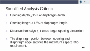
Kimberly noted that a simplified analysis criteria was developed by the Canadian Wood Council after extensive research on shear forces in flexible wood diaphragms with openings. This criteria allows for the diaphragm to be designed for a 10% increase in the maximum shear force if all four criteria are met. The four criteria are included on the slide below:
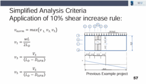
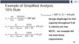
The maximum aspect ratio requirement in the fourth criteria can be found in SDPWS Table 4.2.2. If these four criteria are met, the maximum shear in the diaphragm must be calculated, as demonstrated below:
The shear is calculated along the edge of the diaphragm as well as each edge of the opening, and the largest shear is selected. Then, it is increased by 10% and then the entire diaphragm is designed for this increased shear force.
This useful design procedure can save time when the diaphragm opening meets these basic four conditions. This procedure eliminates the need to complete a detailed Truss Frame Analysis of the diaphragm and provides a simplified design for the entire diaphragm based on an increased shear force throughout. Although this procedure does not currently appear in any US building codes, the research is useful to determine when a more detailed analysis should be performed. To learn more about this research performed by FP Innovations and the Canadian Wood Council, you can read the full report here.
In October 2024, SEU welcomed Matthew Fadden, PhD, PE, from WJE, and Andrea Shear, PE, from Murray Engineering, to present Identifying, Evaluating, and Correcting Punching Shear Deficiencies in Flat Plate Construction. Matt and Andrea have designated the Dick Woods Student Impact Fund (Dick Woods Student Impact Fund – 338683 – Michigan Giving) for our SEU Speaker Inspires donation for the month.
The Dick Woods Scholarship Fund exists to honor of Professor Woods (1935-2021) and his willingness to help CEE students in need. The fund supports students with a demonstrated financial need.
Thank you, Matt and Andrea, for helping structural engineers with your SEU session, and for your designation of the Dick Woods Student Impact Fund at the University of Michigan as our SEU Speaker Inspires Organization of the Month!
SEU began the SEU Speaker Inspires program in 2015 as a way to “pay it forward”, enabling our speakers to designate a charity/organization of their choice for SEU to make a donation to help improve our world.
28 Apr 2025
Wind Loads for Temporary Structures
Temporary structures can be an enigma for structural engineers. ASCE 7 does not directly address temporary structures, so engineers are left to their own judgment to determine the appropriate wind load provisions to use.
In the March 2025 SEU session, Emily Guglielmo, PE, SE, from Martin/Martin, presented Refining Wind Load Approaches for Non-building Structures. Emily reviewed the applicability of ASCE 7 wind load provisions for rooftop equipment, screenwalls, PV panels, signs and canopies, and other non-building structures. She also addressed ways to approach wind loads on structures not explicitly addressed in ASCE 7 such as trellises, tall parapets, and balcony rails. Emily presented rational analysis strategies to address gaps in code provisions for non-building structures and industry best practices.
Emily noted that, in the past, there was no nationally recognized standard that addresses wind load provisions for temporary structures. More recently, a proposal was initiated through IBC to use ASCE 37 Design Loads on Structures during Construction which includes minimum design loads on buildings and other structures during construction. ASCE 37 does allow for a reduction in wind loads. However, this was strongly discouraged by SEI within the committee meeting for two reasons. First, there is an implied risk while on a construction site which does not exist in public venues which are typically housed in temporary structures such as tents with platforms and bleachers. Second, these temporary structures typically travel and are used countless times over the span of many years. This extended life of the structure, although only used in short, temporary circumstances, increases the chance of high speed wind loads on the structure. Thus, SEI put together a group of experts who studied and issued guidelines which are now included in the body of IBC 2024 and will be included in a future Chapter 35 of ASCE 7-28. Check out these new guidelines in IBC 2024 until they become part of ASCE 7 the next time you have a temporary structure to design.
28 Apr 2025
Engineers’ Duty of Confidentiality
Engineers may often be confronted with competing duties of confidentiality, especially between clients or other engineering professionals. How can you establish which confidentiality rules apply and when they take precedence over other ethics rules? To whom does the engineer owe confidentiality?
In the February 2025 SEU session, Matthew Rechtien, PE, Esq., from Walter P Moore, presented Mum’s the Word: 2025 Engineering Ethics Update: Engineers’ Duty of Confidentiality. Matt explained the origins of, and policies behind, engineers’ duty of confidentiality. He described common applicable confidentiality rules and their common features and he demonstrated how to apply such confidentiality rules.
Matt noted that engineers may be subject to multiple jurisdictions in regard to ethics rules, such as state board rules as well as professional member organizations. These rules may differ, thus, engineers should educate themselves on their individual responsibilities in regard to their duty of confidentiality to their clients and the public.
To hear Matt’s thought process, as he walks through a possible example of an engineer facing a confidentiality quandary, click on the video below:
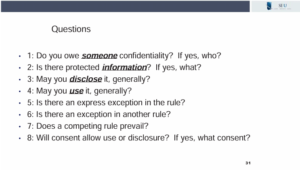
Matt’s algorithm of questions can be especially useful when faced with competing rules or tension between competing loyalties. Click on the slide below to print your own copy to use when comparing the various confidentiality rules which may apply to your unique situation or state. Click on these links to access NSPE’s Code of Ethics, which addresses confidentiality in Section III.4, and Section 4e in ASCE’s Code of Ethics. State laws will vary on this issue, so engineers should take care to spot potential conflicts to avoid disclosing or unethically using confidential information.
Engineers are not often exclusively responsible for locating wall openings on their masonry design projects. However, they are responsible for advising the owner on ways to minimize labor and material costs on the job. There are many strategies which can reduce unnecessary costs in masonry construction, but are you aware of a simple change which can result in massive savings on masonry construction projects?
In the September 2024 SEU session, Scott Walkowicz, PE, from Walkowicz Consulting Engineers, presented Masonry Design and Detailing: Using Your Owner’s Money Wisely. Scott discussed the structural performance benefits and building improvements achieved through the use of masonry, as both a structure and an outer envelope. He identified ways to reduce cost and minimize material waste in masonry design and detailing. He also examined masonry details to create functional, durable, and constructable masonry assemblies.
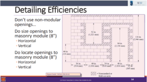
A huge cost savings on masonry jobs can be eliminating the need for saw cutting blocks to accommodate off-modular spacing or openings. Scott mentioned that up to 1-3% of the masonry package can be spent on the labor costs associated with saw cutting blocks. A best practice to minimize these additional costs is for engineers and architects to specify openings and spacing of openings to align with modular blocks. As shown in the slide below, a significant number of blocks would require saw cutting when openings are located offset from the modular spacing.
A better layout is shown below, which locates the opening both horizontally and vertically to avoid off-module saw cuts. On a standard job site, masonry suppliers include a certain number of half-blocks, which eliminates the need for saw cutting when everything aligns with standard unit sizing.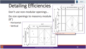
Engineers can also advocate to architects to consider this issue early in the design process. Reducing saw cuts on the jobsite will always result in a lower cost for the owner, so consideration should be given to maintaining proper modular spacing for openings.
In September 2024, Scott Walkowicz, PE, from Walkowicz Consulting Engineers, presented Masonry Design and Detailing: Using Your Owner’s Money Wisely. Scott nominated the The Masonry Society (TMS) (Clayford T. Grimm, P.E. Student Scholarship – The Masonry Society) for the SEU Speaker Inspires donation of the month.
Scott shared, “I chose The Masonry Society (TMS) because of the great work that is done by TMS and its members. I obtained my first degree, a BS in Architecture, and I then wanted to learn how to ‘engineer’ masonry. I attended Clemson University and was able to receive not only a BS in Civil Engineering, but also an MS in Civil Engineering with an emphasis on masonry and interaction with one of TMS’s Honorary Members. The Master’s level coursework and the project that I worked on were extremely valuable to me and my career. I’m very happy to help other engineering students who are seeking Master level degrees and doing research that will benefit both them and the masonry industry.”
Thank you, Scott, for helping structural engineers with your SE University session, and for your designation of the The Masonry Society (TMS) as our SEU Speaker Inspires Organization of the Month!
SE University began the SEU Speaker Inspires program in 2015 as a way to “pay it forward”, enabling our speakers to designate a charity/organization of their choice for SE University to make a donation to help improve our world.
 SE Solutions is pleased to announce the recipients of the SE Solutions + SE Impact structures scholarships at Purdue University as Kyra Fales and Hafdís Magnúsdóttir. This is the twelfth year that SE Solutions has offered the scholarships.
Kyra Fales received her bachelor’s degree in civil engineering with an emphasis in structures from Purdue University in May 2024. She also graduated with minors in Global Engineering Studies and Spanish for the Professions. She is now continuing her education at Purdue through their 4+1 program and will graduate in May 2025 with her master’s degree. During her undergraduate degree, Kyra co-oped as a bridge engineer in Indianapolis, and she will be returning there this summer to begin full-time work. Outside of school, she likes to play soccer, hike and travel.
Hafdís Magnúsdóttir is from Iceland and received her B.S. degree in Civil Engineering from Purdue University in Spring 2024. She is currently pursuing an M.S. degree through the 4+1 program, with expected graduation in Spring 2025. After graduation, she will be joining KPFF in Indianapolis as a structural engineer. She has gained hands-on construction experience by working for a construction company in Iceland for the past four summers. At Purdue, she served as a Resident Assistant and as a Marshall in Chi Epsilon. She was also involved in undergraduate research with the Resilient Extra-Terrestrial Habitats Institute (RETHi), a NASA-funded research group. As part of this research, she designed and built an internal structure to support a testing bladder inside a physical test model and created a 3D SolidWorks model for presentation purposes. Outside of academics, Hafdís enjoys hiking with her dogs, Max and Moose, and playing handball.
SE Solutions would like to congratulate each recipient and wish them future success in their fields of study as structural engineers.
22 Jan 2025
Effective RFPs for Geotechnical Reports
When the Geotechnical engineer is first engaged to provide a geotechnical report, they are often working off of limited project information and may not have a clear vision of the proposed structure. Without detailed project information, the geotechnical report might not provide all of the information the structural engineer requires, and may lead to the structural engineer having to make generalized assumptions about the site specific soil conditions. How then can structural engineers-of-record ensure they get the information they need on projects when there is no national standard for what is included on geotechnical reports?
In the December 2024 SEU session, Andrew Walters, PE, from American Engineering Testing, presented Guide to Understanding a Project Geotechnical Report. Andy explained the importance of a project geotechnical report to various members of the project team, and described the field exploration methods and tests commonly used as part of a project geotechnical evaluation. Andy offered guidance on achieving the information needed in a project geotechnical report and the importance of understanding the report in its entirety.
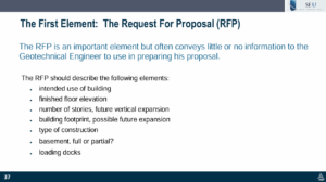
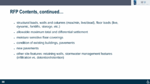
Andy suggested that structural engineers become involved early on in the project with the RFP for geotechnical services. There are many important elements that would be useful for the geotech engineer to form the basis of an RFP. As shown in the slides below, the intended use and future building expansion plans, intended structural loads, and unique project elements should all be noted so the geotech can make appropriate recommendations.
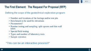
After providing detailed project information, the RFP should also include the intended scope of the geotechnical services. This is especially helpful when comparing RFPs from different geotech firms. Having conversations early on and often with a geotechnical engineer can provide insight into which services would be needed based on the unique aspects of the project.
Structural engineers are not always included in these early discussions when owners and architects launch a new project. However, one of the first aspects the structural engineer-of-record should engage on the project team is a competent geotechnical engineer to ensure the necessary information is obtained for the site specific soil conditions. Communication early in the project can produce a useful and complete geotechnical report.

