29 Jun 2026
TnA Bolts a New Option in AISC 360-22
A new option for a high strength fastener has been included in AISC 360 and engineers may be interested in the benefits of using this new system. With the possibility of saving on material and labor costs, the new TnA bolt could be a solution on your next project.
In the March 2026 SEU session, Matt Mester, PE, SE from MiTek, Inc. presented Changes to Steel: ASIC 360 and 341 Code Updates. Matt reviewed when the building code requires the use of AISC 360/341-16 versus AISC 360/341-22. He noted significant changes in AISC 360 and 341 and described some of the new structural systems and materials/grades that are allowed in the new AISC 360 and 341.
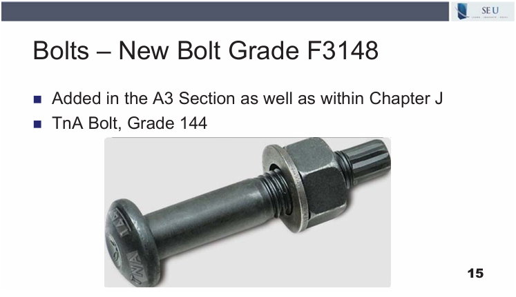
Matt noted the addition of a new bolt in AISC 360 which meets the ASTM F3148 specification. The torque and angle bolt, or TnA bolt, grade 144 has been added in the A3 section as well as within Chapter J. The TnA bolt installation process ensures each bolt is installed to an accurate snug tight condition and then is turned to the required angle to reach a precise final tension. The new bolt offers more reliability than a typical snug tight installation. The TnA bolt grade is 144 which falls between the popular A325 bolt which is grade 120 and A490 bolts which are grade 150. The higher strength could require the use of less bolts compared to the standard A325, which could reduce costs.
As you can see in the slide below, this new bolt has a stub on the end which is similar to a Tension Controlled bolt. However, while the TC bolt stub falls off once the bolt reaches the required pretension force, the stub on the TnA bolt remains in place even after the bolt is torqued to a snug tight condition. This could be a potential downside on jobs where the design tolerances are quite minimal, and the remaining stub could cause a conflict. However, it also allows for removal of the bolt using the same wrench which could be an advantage, especially in structures that may be temporary in nature. The addition of the TnA bolt to the specification gives engineers a new option for a fastener with a mid-grade strength.
29 Jun 2026
Ethical Advice and Decision Making
Being ethical can be hard. Professional engineers are tasked with sound engineering judgement as well as protecting the safety and welfare of the public. Structural engineers often face ethical dilemmas that can be murky waters to navigate. From whom can engineers seek wise counsel regarding ethical dilemmas?
In the February 2026 SEU Ethics session, Barry Arnold, PE, SE, retired from ARW Engineers, presented 8 Tips to Avoid the Traps of Unethical Behavior. Barry explained the fundamental purpose and principles of the Code of Ethics. He described 8 tips to build a solid ethical foundation and improve one’s ethical IQ, and identified resources to aid in ethical decision making.
Barry gave an important tip for engineers who are faced with an ethical dilemma. After confronting and understanding the problem, engineers need to be aware of their own and other’s biases. To hear Barry explore the importance of this tip, watch this short video:
Seeking advice on ethical dilemmas requires introspection and careful examination of the biases of yourself and others. In most cases, it would be valid to seek out multiple opinions from trusted sources and unbiased third parties to try to eliminate any conflicts of interest in ethical decision making. Each instance requires a unique perspective because ethical dilemmas are so varied and nuanced and engineers typically are not well seasoned on dealing with ethical issues, especially newly licensed engineers. Barry rightfully recommends examining the biases and motivations of those in whom one seeks advice when faced with ethical dealings to avoid self interests or covert coverups.

Sam Rubenzer, SE, PE, FORSE Consulting
In November 2025, SEU welcomed back Sam Rubenzer, SE, PE, from FORSE Consulting, to present Welcome to the New Age of Delegating the Design of Masonry. Sam has designated the National Military Family Association (Serving Military Families Since 1969) for our SEU Speaker Inspires donation for the month.
Sam designated the National Military Family Association in honor of the recent Veteran’s Day holiday, as well as a tribute to his family members who are veterans and active military members. NMFA meets the immediate needs of America’s military families with programs designed to support their financial security, well-being, and quality of life, as well as advocating for support from our government officials to serve the unique needs and challenges of service members of all branches of our US military.
Thank you, Sam, for helping structural engineers with your SEU session, and for your designation of the National Military Family Association as our SEU Speaker Inspires Organization of the Month!
SEU began the SEU Speaker Inspires program in 2015 as a way to “pay it forward”, enabling our speakers to designate a charity/organization of their choice for SEU to make a donation to help improve our world.
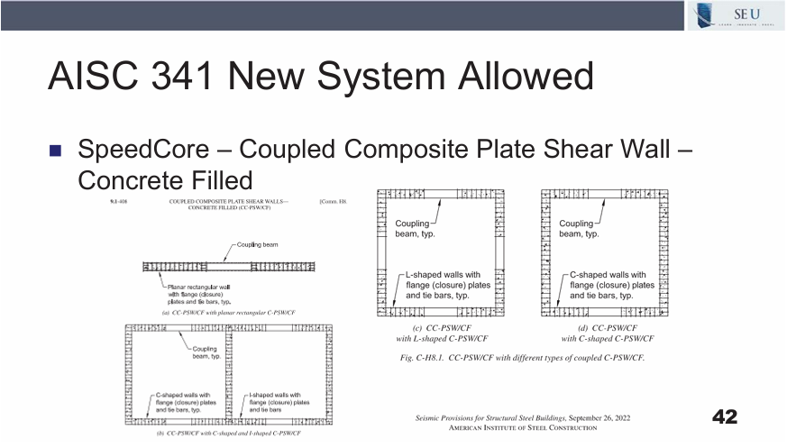
Are you aware of the new concrete filled composite plate shear wall system included in AISC 341-22? This new structural system could offer significant financial savings on concrete mid- and high-rise structures in high seismic regions where this system would offer the most benefit.
In the March 2026 SEU session, Matt Mester, PE, SE from MiTek, Inc. presented Changes to Steel: AISC 360 and 341 Code Updates. Matt reviewed when the building code requires the use of AISC 360/341-16 versus AISC 360/341-22. He noted significant changes in AISC 360 and 341 and described some of the new structural systems and materials/grades that are allowed in the new AISC 360 and 341.
The SpeedCore system consists of coupled composite plate shear walls which are filled with concrete. The use of steel plates as the form work for the concrete eliminates the use of traditional steel rebar within the shear wall. The SpeedCore walls are pre-fabricated off site and then brought to the site, welded together, and then concrete is poured into the cavity. On traditional concrete high rise structures, the forms are built on site, the rebar is placed and tied within the forms, the concrete is poured, and then must cure for a specified time before the forms can be removed and then moved up the building to start the next level. The SpeedCore system increases the speed of construction by eliminating the use of traditional forms with rebar, and the time needed to cure before construction can move up the building.
To learn more about using the SpeedCore system, you can download AISC Design Guide 38: SpeedCore Systems for Steel Structures which is free for members or available for purchase for non-members. Also, Structure Magazine highlighted the use of SpeedCore in Seattle’s Rainier Square and the cost savings compared to using traditional concrete construction methods.
While SpeedCore may not be necessary or the most cost effective solution on every job, there are instances where the use of this new structural system could be a novel solution to increase speed of construction and reduce labor and material costs.
Kimberly W. Kramer, PhD, PE, Kansas State University
In October 2025, Kimberly W. Kramer, PhD, PE, SE, from Kansas State University, presented Designing for Openings in Wood Diaphragms. She nominated ACI Foundation (ACI Foundation > Home) for the SEU Speaker Inspires donation of the month.
Kimberly shared, “I selected the ACI Foundation because concrete is the most widely used building material in the world, and the Foundation is driving the research, innovation, and student support that will shape its future. ACI has played a meaningful role in my own career, and I’ve seen firsthand how their scholarships, mentoring, and technical advancements open doors for young professionals and strengthen our industry. Supporting the ACI Foundation allows me to give back while helping ensure a more resilient, sustainable, and well-prepared generation of concrete leaders.”
Thank you, Kimberly, for helping structural engineers with your SE University session, and for your designation of ACI Foundation as our SEU Speaker Inspires Organization of the Month!
SE University began the SEU Speaker Inspires program in 2015 as a way to “pay it forward”, enabling our speakers to designate a charity/organization of their choice for SE University to make a donation to help improve our world.
Significant changes have been made to the ground snow loads in Chapter 7. What prompted these changes and why were they necessary?
In the February 2026 SEU Session, Scott Russell, SE, PE, from Vulcraft, presented ASCE/SEI 7-22 Snow & Rain Loading with Suggestions on Joist Specification. Scott described significant updates to the snow provisions in ASCE 7-22 and identified new provisions for thermal factors, snow drift heights and windward drifts widths and how to apply them. He also explained the revised rain load calculation methodology in Chapter 8 and reviewed how to specify joists and joist girders for these new changes to ASCE 7-22.
The primary purpose of the changes in Chapter 7 of ASCE 7-22 aim to achieve uniform failure probability through a reliability-targeted ground snow load. While previous ground snow load maps were based on too few data samples to be accurate for local use, modern snowfall data collected throughout the last 40 years include 500,000+ ground snow load values which have been scrutinized and evaluated. The data from each weather station is used to produce reliability-targeted loads that seek to estimate the probability that the Random Resistance minus the Random Roof Load is less than zero, as shown in the slide below.
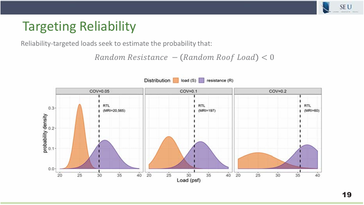
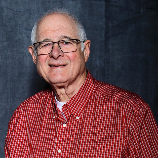
As you can see at the top of the graphs, the different Coefficient of Variation can drive different Mean Recurrence Interval values which is why it is not accurate and efficient to use the same MRI value of 50% throughout the entire United States. This variation can be shown in the graphs below, which note the differences in snow behavior in three different cities depending on typical snow behavior vs extreme snow behavior.
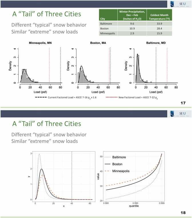
As a result of this newer data set being collected and analyzed, four new ground snow loads maps have been included in ASCE 7-22, one for each of the four Risk Categories. The ASCE Hazard Tool is the easiest and most accurate way to establish the new ground snow load for your building location. This major update to Chapter 7 in ASCE 7-22 will help eliminate the need for local authorities to adopt other snow load guidelines, and provide more appropriate loads based on eco-regions rather than arbitrary state lines.

Josh Canova, PE, New Millenium

Victor Esty, Canam Steel
In September 2025, SEU welcomed Josh Canova, PE, from New Millenium, and Victor Esty, from Canam Steel, to present Properly Specifying Steel Deck. Josh and Victor have designated One More Child (https://onemorechild.org/) for our SEU Speaker Inspires donation for the month.
Josh shared, “As a husband and father who is not only blessed with a family but blessed to be able to provide for my family, I wanted to choose an organization that supports and cares for those who have had a tougher go at things and find themselves in difficult situations. One More Child is a faith-based organization that serves the most vulnerable in our society by supporting children in need, combatting human trafficking, and providing support for single moms or families in need.”
Thank you, Josh and Victor, for helping structural engineers with your SEU session, and for your designation of One More Child as our SEU Speaker Inspires Organization of the Month!
SEU began the SEU Speaker Inspires program in 2015 as a way to “pay it forward”, enabling our speakers to designate a charity/organization of their choice for SEU to make a donation to help improve our world.
26 Feb 2026
“SEU Speaker Inspires” Organization of the Month: Thomas M. Murray Structures Laboratory at Virginia Tech
Dave Samuelson, PE Nucor

Joe Pote, PE New Millenium
In August 2025, SEU welcomed Joe Pote, PE, from New Millennium, and Dave Samuelson, PE, retired from Nucor, to present Composite Floor Joist Systems. Joe and Dave have designated the Thomas M. Murray Structures Laboratory at Virginia Tech (Home | Structural Engineering and Materials | Virginia Tech) for our SEU Speaker Inspires donation for the month.
Joe and Dave shared, “Dr. Thomas M. Murray was instrumental in coordinating steel joist research documenting the behavior of the Steel Joist Institute’s CJ-Series composite steel joists and floor vibration of steel joist supported concrete floor systems. With Dr. Murray’s recent passing in August 2024, it is appropriate to honor the Thomas M. Murray Structures Laboratory for completing the above-mentioned steel joist research as well as continuing research of steel structures. Thanks to Dr. Murray’s vision, the Thomas M. Murray Structures Lab continues to be used for structural research, and we continue to build on the foundational research performed by Dr. Murray.”
Thank you, Joe and Dave, for helping structural engineers with your SEU session, and for your designation of Thomas M. Murray Structures Laboratory at Virginia Tech as our SEU Speaker Inspires Organization of the Month!
SEU began the SEU Speaker Inspires program in 2015 as a way to “pay it forward”, enabling our speakers to designate a charity/organization of their choice for SEU to make a donation to help improve our world.
26 Feb 2026
PT Design Resources
Are you just getting started on a new post-tensioning design project? Are you able to quickly establish some basic slab thickness guidelines early on in your PT projects, or are you looking for great resources to guide the early schematic design phase of your projects?
In the December 2025 SEU session, Carine Leys, from WSP, presented The Design Arc of Post-Tensioning. Carine explained how to evaluate during the conceptual phase if post-tensioning is a structural solution that meets the project’s performance requirements. She reviewed ways to develop comprehensive documentation relevant to each phase of the project and identified best practices during construction to ensure safety and durability.
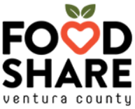
Carine offered several resources for PT design as shown on the slide below. These include Restraint Cracks and Their Mitigation in Unbonded Post-Tensioned Building Structures from PTI. This document provides details and considerations for pour strip placements, duration of pour strips, and details to mitigate cracks. Carine also recommends the Post-Tensioning Manuel, Seventh Edition, from PTI. This reference is excellent for early preliminary sizing and examples to use without having to do much analysis, especially early on in the schematic phase of a project. This is especially useful if the engineer does not yet have years of experience with PT design.
The two additional resources Carine mentioned are Post-Tensioned Buildings Design and Construction and Post-Tensioning Concepts; Design; Construction, both by Bijan O. Aalami. These references are useful and practical for the design engineer during the design and construction phase of PT projects.
 SEU / SE Solutions is pleased to support two charitable organizations in 2025 which directly support children and families in Lisa’s local community as well as across the country. Lisa selected Goods4Greatness and Food Share Ventura County to receive these donations, and we are thankful to our SEU community for making this community support possible.
Lisa shared, “As a parent, I fully believe kids need to have “their thing,” whether that is playing an instrument, doing volunteer work, or participating in a sport. About 10 years ago, I was the President of a Youth Track Club, and I saw how many families were asking for help with league fees. At the same time, I saw how expensive it was to buy equipment for different teams – and that’s just for shoes (basketball shoes, soccer cleats, baseball cleats, spikes)! I worried about the kids who weren’t able to afford to participate, and hated the idea that cost was a barrier to sports. I had the idea of creating an organization to help kids afford sports equipment and league fees, but as I searched the internet for ideas, I found Goods4Greatness. It was started by a sports reporter who used to write for our local newspaper, and although she had moved across the country, she still supported our local schools and leagues, helping buy Balls, Racquets, Shoes, etc. for kids who wouldn’t otherwise be able to afford it. I love seeing the impact that G4G is able to make locally, and across the country.” To learn more about Goods4Greatness, visit their website to see the change they are making across our country.
 Regarding Food Share, Lisa said, “Food Share helps local families in Ventura County by distributing over one million pounds of food per month, operating food pantry sites, drive through food pick-up, hot meal locations, and more. Especially in times when food costs are rising, leading to more families feeling the pressure of being able to afford nutritious food, Food Share provides options, in their own words, “Because no one should go hungry,” and I’m grateful for the work they do in our community.” To learn more about Food Share, visit their website to see their impact in Ventura County.
SEU / SE Solutions is proud to support these charitable organizations and look forward to making a bigger impact for good in our country in 2026.