30 Nov 2025
Steel Deck: Finish or Coating?
When should steel deck be galvanized versus shop coated? Does one finish provide more protection than the other? And what considerations should impact which deck type to select?
In the September 2025 SEU session, Joshua Canova, PE, from New Millennium, and Victor Esty, from Canam Steel Corporation, presented Properly Specifying Steel Deck. Joshua and Victor identified resources that are available to help specify steel deck and reviewed the design considerations for selecting steel deck profiles. They highlighted proper expectations of steel deck finish performance and appearance, and described what to avoid when specifying steel deck.
Josh reviewed the available options for steel deck finishes and coatings. As you can see in the slide below, there are 5 options to explore when specifying steel deck, depending on the use, function, and environment of the structure.
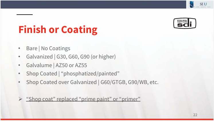
Bare deck can be used in roof deck, form deck, or composite deck floors. As the name implies, the deck is bare and does not have any protective coating applied. A bare deck is more prone to the deleterious effects of water or caustic chemicals in the environment, but may be entirely appropriate for indoor and well protected decks.
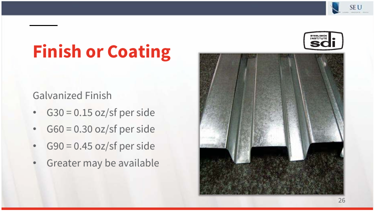
Galvanized deck is a carbon steel deck that has been finished with a zinc coating which protects the steel from rust by acting as a sacrificial barrier between moisture and the steel. Galvanized steel deck is typically available in G30, G50, or G90, which denotes the amount of zinc applied per square foot as shown in the slide below. Galvanized steel is the most common specified steel deck, especially in outdoor or moisture-rich environments. Galvanized deck may be used in roof, form, or composite decks. Touch up with zinc-rich paint may be required where damage to the finish occurs in the field, but is not usually necessary for small nicks or scratches. Galvanized deck is more expensive than bare deck and about 20% more than a shop coated deck. Galvalume is a similar product, typically used in roofing applications, which consists of carbon steel hot-dipped with layers of zinc and aluminum to achieve a durable and corrosion resistant deck.
Shop coated deck refers to carbon steel deck that has been painted with a primer. Typically gray and/or white primer is available, although some manufacturers may offer other colors. The shop applied primer is intended to act as the barrier to protect the steel, but a final field applied paint should be used when necessary for aesthetic purposes. Galvanized deck can also be shop coated to provide additional protection and a more aesthetic finish. Roof, form, and composite deck are all available with a shop coated primer, however, it is important to note that the top side of composite deck should not be specified to be shop coated. The composite action of the concrete and deck cannot be achieved with a shop coated steel, as the coating allows for slippage to occur between the deck and the concrete.
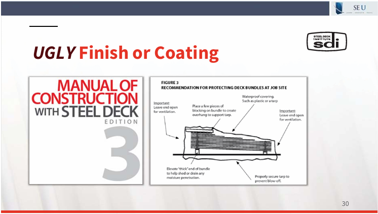
All steel deck should be protected when stored on job sites to prevent environmental damage. As you can see in the slide below, the deck should be covered, elevated, and sloped to allow air flow and moisture flow, to prevent rust or staining from occurring.
The structural engineer should also consider other options when the deck will be used in corrosive environments. This could include some agricultural, industrial, or high humidity environments, as well as exposure to chemicals such as chlorine, acids, or ammonia. Steel decks exposed to these corrosive environments should be well protected by the addition of barriers or coatings, or the engineer should consider stainless steel. Also, ventilation will be critical to minimizing the deleterious effects in a corrosive environment.
Properly specifying steel deck is critical to ensuring an appropriate life cycle of the deck. A deck which has not been protected with finishes or coatings could lead to unwanted corrosion and reduce the load capabilities of the deck. Engineers should consider the use, function, and environment in which the deck will be exposed before specifying criteria for the coating or finish of the steel deck.
30 Nov 2025
Happy Thanksgiving from SE Solutions!
We would like to take this opportunity to thank our SE Solutions community and hope everyone enjoyed a wonderful Thanksgiving holiday. SE Solutions and SEU are thankful to our clients and speakers who have made it possible for us to contribute to many charitable organizations during the past year through our SEU Speaker Inspires program.

Kimberly W. Kramer, PhD, PE, Kansas State University
In April 2025, Kimberly W. Kramer, PhD, PE, SE, from Kansas State University, presented Designing for Openings in Wood Diaphragms. She nominated Purple Power Animal Welfare Society (Purple Power Animal Welfare Society Rescuing Homeless Pets) for the SEU Speaker Inspires donation of the month.
Kimberly shared, “I selected Purple Power Animal Welfare Society because of the incredible work they do as an all-volunteer, foster-based rescue organization that supports no-kill shelters for homeless cats and dogs in the Manhattan and Junction City area. Their outreach programs, like Pet Away Stress in partnership with K-State Counseling Services and P.A.W.S., bring therapy dogs to campus to help students recharge during high-stress times like midterms. I also value how their mission aligns with Kansas State University’s commitment to animal care, including programs like the Perpetual Pet Care Program in the College of Veterinary Medicine, which ensures pets receive a lifetime of medical care and loving homes when owners are no longer able to provide care. Supporting Purple PAWS is a meaningful way to positively impact both animals and our community.”
Thank you, Kimberly, for helping structural engineers with your SE University session, and for your designation of Purple Power Animal Welfare Society as our SEU Speaker Inspires Organization of the Month!
SE University began the SEU Speaker Inspires program in 2015 as a way to “pay it forward”, enabling our speakers to designate a charity/organization of their choice for SE University to make a donation to help improve our world.
Are you aware of the many advantages of using open web steel joists to achieve a high performance floor? In many cases, steel joists are an economical solution to reduce the overall steel weight, reduce floor-to-floor heights, reduce costs, and produce a flatter finished floor with improved vibration characteristics. In the past, engineers have faced vibration issues using open web steel joists, due to the lighter overall floor system, however, improvements in design and construction techniques have leveraged the advantages of steel joists to produce an economical and better performing building structure.
In the August 2025 SEU session, Joe Pote, PE, from New Millennium, and Dave Samuelson, PE, retired from Nucor, presented Composite Floor Joist Systems. Joe and Dave explained what spacings and depths work best for open web steel joists in floors and how to decrease the floor-to-floor height while increasing the joist depth. They also discussed the advantages of flush-frame joist connections in floor construction. Joe and Dave shared a useful new tool which compares the performance and costs of different steel framing options which is now available through the Steel Joist Institute (SJI).
Available as a free download from SJI, the Floor Bay Comparison Tool – With Vibration can be used to analyze composite and non-composite systems composed of joists and joist girders or hot-rolled steel sections. The tool also does a vibration analysis and allows the user to compare options to improve the vibration performance of the floor bay. As you can see below, the user must specify the geometry of the bay, as well as loading conditions, deck and slab selection, deflection criteria, and depths of the joists, beams or girders.
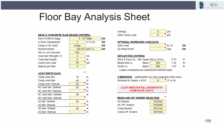
To understand the specifics of this tool, the user should first read the Gen Info sheet which answers many FAQs and provided references, and then review the User Notes which explains recommendations, including many related to improving vibration performance. After the floor bay has been analyzed, the user is provided with comparison tables noting the lightest option, peak acceleration ratios, natural frequencies and limit checks are listed and compared, including options for different joist seat depths or flush mounted joists, which can significantly reduce vibrations. The user can then make educated selections for joists or beams, composite or non-composite, to achieve desired floor-to-ceiling heights while reducing overall weight and minimizing vibrations.
SJI provides a number of other design tools which are available as free downloads at their website. Check out these free tools on your next project using joists and joist girders to save valuable design time and lower costs. Another excellent resource is SJI’s Technical Digest 13 – Specification and Design of Composite Steel Joists which includes the design methodology of CJ-Series Composite joists and can be purchased from SJI for use in conjunction with the Second Edition CJ-Series Composite Steel Joists catalog, which is available as a free download.
27 Oct 2025
Flush-Frame Joist Connections
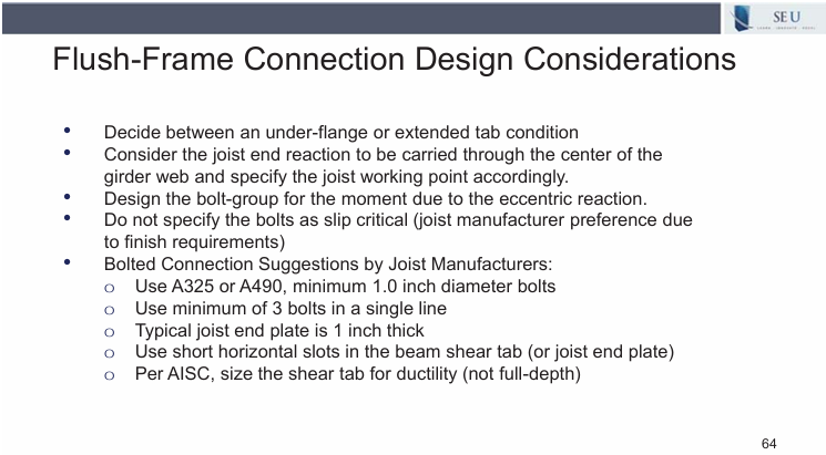
Are you aware of the many advantages of using flush-frame connections for open web steel joists? Not only are flush-frame connections an excellent solution to improve the composite action of girders, they also facilitate panelized erection which can reduce multi-story erection times by half. The floor-to-floor heights are also reduced and flush-frame connections eliminate the need for blocking between joists to transfer shear since the slab is in direct contact with the girders.
In the August 2025 SEU session, Joe Pote, PE, from New Millennium, and Dave Samuelson, PE, retired from Nucor, presented Composite Floor Joist Systems. Joe and Dave explained what spacings and depths work best for open web steel joists in floors and how to decrease the floor-to-floor height while increasing the joist depth. They compared the performance of composite and non-composite joists, and they discussed the advantages of flush-frame joist connections in floor construction.
The significant increase in the use of flush-frame joist connections in the post-Covid boom of e-commerce multi-story office buildings resulted in every major US joist manufacturer learning to mass produce this new joist connection. Using flush-frame joist connections allows the steel deck and concrete slab to be in direct contact with the girder top flange, thus developing the full composite moment of inertia with no reduction from an elevated concrete slab as is the case with a standard joist seat. This results in a more effective girder size and improves the vibration performance of the floor system.
Joe noted there is no standard design procedure offered by SJI for flush-framed connections, however all major joist manufacturers have developed their own design procedures, and many resources are available to aid in the design of flush-frame connections. Joe walked through the process used by New Millennium, and offered some design considerations for the EOR.
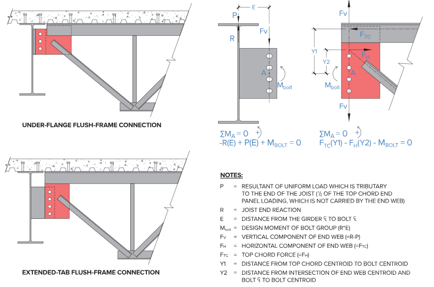
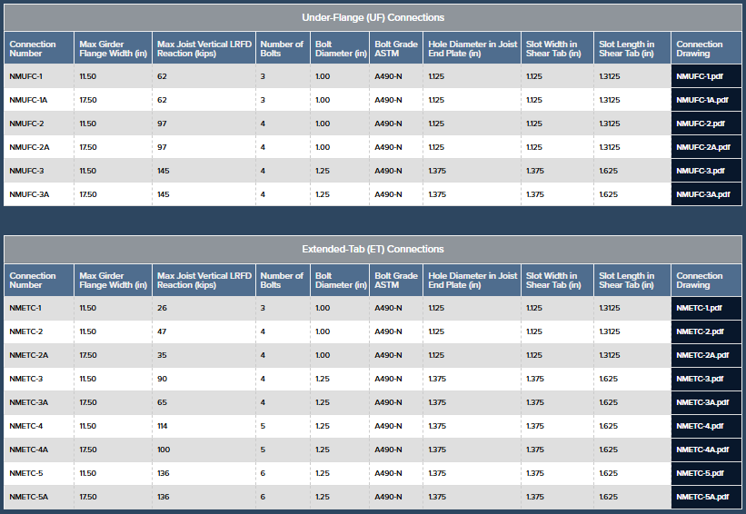
Under-flange and extended tab connection tables, as shown below, are offered by joist manufacturers which can be used as design aids to expedite the design process. Although the EOR is solely responsible for the design of the joists and its connections, the joist manufacturer can provide calculations for each of their standard flush-frame connection details to the EOR. New Millennium also offers a Flush-Frame Design Guide on the use of these connections which can be downloaded from their website.
Flush-frame joist connections are used in up to 90% of composite joist floor construction in the US today. Their ability to reduce floor-to-floor heights while improving floor vibration performance, and facilitate the use of panelized erection during construction has prompted a major shift in the design of large scale, multi-story office floor systems.
23 Sep 2025
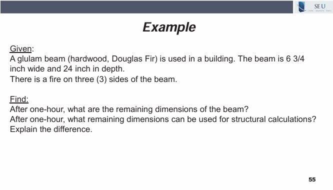
After the Fire: What’s Left of the Beam?
Condition assessments after a fire often involve determining the load capacity of the remaining structural elements. Are you familiar with the equations used to determine the effective depth of char and the remaining cross-sectional dimensions as prescribed in the NDS for mass timber structural elements?
In the July 2025 SEU session, Erica Fischer, PhD, PE, from Oregon State University presented Hot Topic: The Fire Performance of Mass Timber. Erica reviewed the current code and standard guidance for the fire protection design for mass timber, and noted current research on mass timber and fire to enable performance-based design. She also summarized some challenges with mass timber and fire.
Erica walked through the following example to determine the depth of char and the effective depth of char for a glulam beam exposed to fire.
To hear Erica explain this procedure, watch this short video:
As Erica explained, it is necessary to use the effective depth of char to account for the zero stiffness layer beneath the char. This effective char depth should be used to calculate section properties on reduced cross-sectional dimensions for structural calculations. These equations for the char depth and effective char depths for sawn lumber and mass timber, as well as CLT can be found in the National Design Specification (NDS) in Chapter 16. While both char depth equations are non-linear and proportional to the nominal char rate, CLT also includes factors to account for the lamination thickness, the number of laminations charred, and the time for the char front to reach the glulam interface, as shown below.
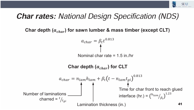
This specific equation used for CLT char depths accounts for known gaps in the layers of laminations which accelerates the char rate and gives additional pathways for the fire to propagate. Engineers should be aware of the difference when using CLT members to account for this acceleration in the char rate, to ensure accurate remaining section properties can be established.

Emily Guglielmo, PE, SE, Martin/Martin
In March 2025, Emily Guglielmo, PE, SE, from Martin/Martin, presented Refining Wind Load Approaches for
Non-building Structures. She nominated SEAOC SE Pathways Program (SE Pathways Intro – Structural Engineers Association of California) for the SEU Speaker Inspires donation of the month.
SEAOC’s SE Pathways to the Profession initiative aims to address the disparity of engagement and lack of diversity within the California structural engineering profession. SE Pathways to the Profession brings together students and early career professionals and engages them in dialog about engagement, retention and equity in the structural engineering profession.
Thank you, Emily, for helping structural engineers with your SE University session, and for your designation of SEAOC SE Pathways Program as our SEU Speaker Inspires Organization of the Month!
SE University began the SEU Speaker Inspires program in 2015 as a way to “pay it forward”, enabling our speakers to designate a charity/organization of their choice for SE University to make a donation to help improve our world.
28 Jul 2025
Stability Bracing and BRBs
Buckling-Restrained Braces are becoming more widely incorporated into seismic designs worldwide. As their use increases, design engineers should be aware of ways to improve the communication and implementation of BRBs into their projects, as well as the code provisions and requirements for the use of BRBs.
In the June 2025 SEU session, Ben Sitler, PE, Dr.Eng., from Buro Happold, presented Seismic Design with BRBs – Pushing to the Limit. Ben noted recent changes to the BRB design and testing provisions of AISC 341-16 and 341-22. Ben explained how BRBs respond in extreme design cases and how to ensure good performance in long and jumbo BRBs, and he reviewed the fundamental behavior of BRBs.
Ben showed how higher-mode buckling and frictional behavior impacts the compressive strains in long BRBs, and how higher strength steel grades may be a valid and even desirable option for large capacity BRBs. He discussed the need for the design engineer to provide stability bracing for BRBs in the scope of their design. While the BRB supplier will perform the necessary stability analysis and physical testing as required on a project-specific basis, the design engineer should communicate with the supplier to discuss what connections or bracing may be required to ensure the BRB is torsionally restrained in both directions. To hear Ben discuss some tips for design engineers providing stability bracing, watch this short video from his presentation:
As Ben discussed, engineers should provide torsional braces and connections on beams framing into BRB connections. Closed beam sections may also be required where diaphragms are absent. Maintaining global stability is essential when using BRBs and the design engineer plays a crucial role in ensuring the framing provided can resist these out of plane forces. Ben also noted that AISC 360 Appendix 6 does provide some guidance on bracing stiffness and strength provisions, however, these were not specifically developed for BRBs and are typically intended for lateral-torsional buckling calculations. While the torsional forces from BRBs are not usually large, they are still present and need adjacent framing to provide resistance.

Brad Davis, PhD, SE, PE, Davis Structural Engineering
In November 2024, SEU welcomed Brad Davis, PhD, SE, PE, from Davis Structural Engineering, to present Vibration Analysis of Steel Joist / Concrete Floors. Previously in 2020, Brad designated Doctors without Borders (https://www.doctorswithoutborders.org/) for our SEU Speaker Inspires donation for the month, and he has chosen to do the same in 2024.
Doctors without Borders, or Medicins Sans Frontieres, provides medical humanitarian aid where the needs are greatest, and often go to places where other organizations can’t or won’t operate. Historically, they have not run medical projects in the US, however in March 2020, MSF launched temporary operations in the United States in response to the unprecedented COVID-19 pandemic. In key sites around the country, MSF is working with local authorities and partner organizations that serve vulnerable communities with limited access to health care, such as migrants, homeless people, and other marginalized or neglected groups
Thank you, Brad, for helping structural engineers with your SEU session, and for your designation of Doctors without Borders as our SEU Speaker Inspires Organization of the Month!
SE University began the SEU Speaker Inspires program in 2015 as a way to “pay it forward”, enabling our speakers to designate a charity/organization of their choice for SE University to make a donation to help improve our world.

Andrea Shear, PE, Murray Engineering

Matthew Fadden, PhD, PE, WJE
In October 2024, SEU welcomed Matthew Fadden, PhD, PE, from WJE, and Andrea Shear, PE, from Murray Engineering, to present Identifying, Evaluating, and Correcting Punching Shear Deficiencies in Flat Plate Construction. Matt and Andrea have designated the Dick Woods Student Impact Fund (Dick Woods Student Impact Fund – 338683 – Michigan Giving) for our SEU Speaker Inspires donation for the month.
The Dick Woods Scholarship Fund exists to honor of Professor Woods (1935-2021) and his willingness to help CEE students in need. The fund supports students with a demonstrated financial need.
Thank you, Matt and Andrea, for helping structural engineers with your SEU session, and for your designation of the Dick Woods Student Impact Fund at the University of Michigan as our SEU Speaker Inspires Organization of the Month!
SEU began the SEU Speaker Inspires program in 2015 as a way to “pay it forward”, enabling our speakers to designate a charity/organization of their choice for SEU to make a donation to help improve our world.