Practical Control Joint Spacing in Masonry Walls
Control joints (CJs) are necessary in reinforced masonry walls with minimal joint reinforcing to prevent thermal cracking. However, improper placement of CJs can negatively impact the structural capacity of the wall and lead to an inefficient design. What are the best methods to ensure an efficient and practically detailed masonry wall with CJs?
In the April 2020 SE University session, Sam Rubenzer, PE, SE, from FORSE Consulting, presented Masonry Checklist: Reviewing Structural Drawings. During the session, Sam offered insight on developing checklists of important items for masonry design and construction. He also reviewed important aspects of masonry design criteria and discussed best practices for element design, including advice on locating control joints and using masonry lintels.
Criteria for CJs in masonry walls will vary in different locations in the country due to different loading demands, and reinforcement and construction techniques common to each area. For example, it is common to have more horizontal reinforcement in high seismic areas and those areas already use less CJs. However, many midwestern states with low seismic loads commonly use minimal horizontal reinforcement only in mortar joints, and therefore require more CJs be used.
There are commonalities for CJ placement within all areas. When placing CJs in masonry walls, Sam noted that placing them too closely will result in shear walls that have significant losses in their lateral resistance capacity; However, spacing them too far apart will potentially result in thermal cracking throughout the wall. Sam offered some basic guidelines for placing control joints for maximum effectiveness.
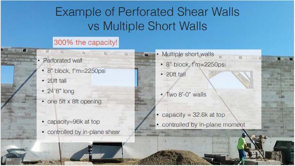
First, CJs should not be placed adjacent to wall openings. As you can see in the example below, a perforated shear wall can have 300% the capacity of two shorter walls being split near the opening.
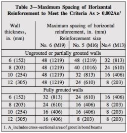
Additionally, you may need to design some walls with increased horizontal reinforcing in order to eliminate some CJs. For example, long walls with repetitive door openings, as shown below, do not offer a practical location for a CJ. Designing these walls with additional horizontal reinforcement can allow the wall to maintain its lateral resistance without the need for a control joint within the area around the doors. NCMA TEK Guide 10-3 provides guidance on horizontal reinforcement requirements.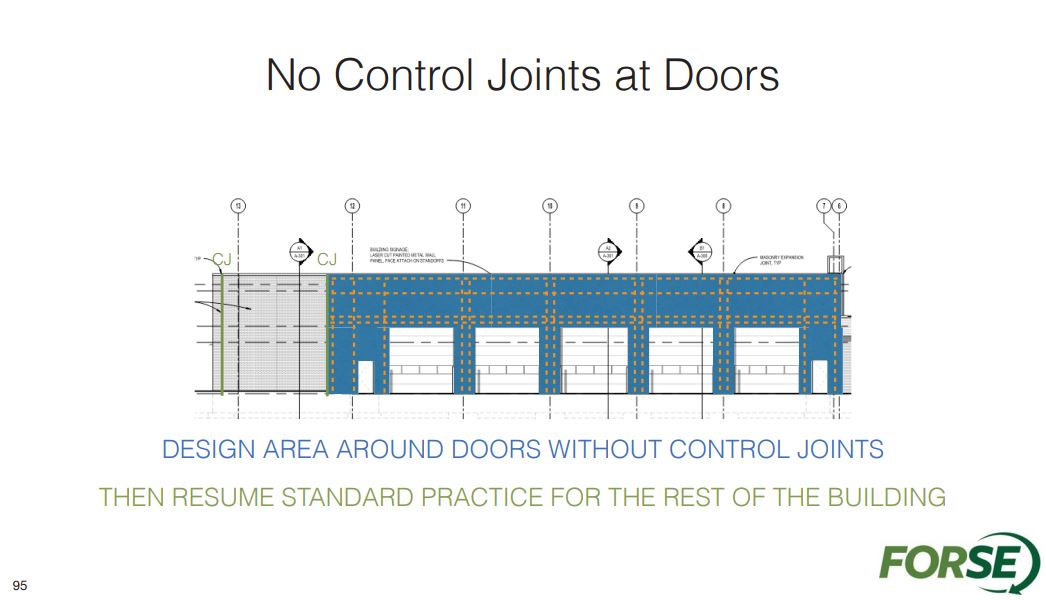
Sam also suggested the use of masonry lintels in order to reduce the need for CJs. Using masonry lintels creates a more rigid wall which eliminates stress concentrations which can develop when using steel lintels with CJs at repetitive wall openings. In the same example above, a continuous masonry lintel further improves the rigidity of the wall, increases the lintel’s capacity to resist load, and increases the wall area’s ability to resist in-plane and out of plane loading. Also, the continuous lintel reinforcement can contribute to the overall reinforcement required to reduce the need for CJs in that area.
Sam strongly recommends showing CJs on plan and/or elevation rather than within structural notes. Also, it can be helpful to delineate these locations on elevation since architects tend to show movement joint location on their elevations, as well. Using these tips from Sam about practical CJ spacing, masonry walls designs become more efficient and stronger and reduce the likelihood for cracks due to thermal movements.
There are no comments yet, but you can be the first