
Roger LaBoube, PhD, PE Missouri University of Science and Technology
In December 2022, SE University welcomed back Roger LaBoube, PhD, PE, from Missouri University of Science and Technology, to present Cold-Formed Steel Standards (2022). In years past, Roger designated the Leukemia and Lymphoma Society (https://www.lls.org/) for the SEU Speaker Inspires donation of the month, and he has chosen to do the same in 2022.
Roger shared: “On June 7, 2003, our daughter Jennifer married Russ. The wedding was a wonderful family event and Karen and I were both extremely happy for Jennifer and Russ. Four short months later, Russ was diagnosed with Hodgkins Lymphoma Stage 4B. After 10 months of treatments, Russ’ Hodgkins was forced into remission. Obviously, Karen and I were elated to learn of this news. However, in June 2005, Russ was diagnosed with leukemia. Following more chemotherapy and a stem cell transplant, the leukemia is now in remission. I chose to support LLS to honor both Russ and Jennifer for their fighting spirit and to help others who are also fighting so hard to defeat their cancer. Our family has benefited first hand from both the research and the patient services of the Leukemia and Lymphoma Society.”
Thank you, Roger, for helping structural engineers with your SE University session, and for your designation of the Leukemia and Lymphoma Society as our SEU Speaker Inspires Organization of the Month!
SE University began the SEU Speaker Inspires program in 2015 as a way to “pay it forward”, enabling our speakers to designate a charity/organization of their choice for SE University to make a donation to help improve our world.

Sam Rubenzer, SE, PE FORSE Consulting
In September 2022, SEU welcomed back Sam Rubenzer, SE, PE, from FORSE Consulting, to present Verifying Software Results. Sam has designated Children’s Minnesota (Children’s Minnesota (childrensmn.org)) for our SEU Speaker Inspires donation for the month.
Children’s Minnesota is one of the largest freestanding pediatric health systems in the United States and the only health system and Level I Trauma Center in Minnesota to provide care exclusively to children from before birth through young adulthood. Sam noted that Children’s Minnesota had done “some really great work for a sweet girl I know!”
Thank you, Sam, for helping structural engineers with your SEU session, and for your designation of Children’s Minnesota as our SEU Speaker Inspires Organization of the Month!
SEU began the SEU Speaker Inspires program in 2015 as a way to “pay it forward”, enabling our speakers to designate a charity/organization of their choice for SEU to make a donation to help improve our world.
23 Feb / 2023
Resilience in Structural Engineering
Are you aware of how structural engineers can improve on a community’s ability to recover from a natural disaster? Community resilience depends on many influencing factors, and the idea of resilient design is a new topic to most structural engineers. With more severe natural disasters affecting our communities in ways we haven’t envisioned, and climate change shifting the cycle associated climatic events, structural engineers need to identify opportunities to be part of the solution and educate themselves to be effective and active participants in resilience.
In the January 2023 SEU session, Kevin Moore, SE, with Simpson Gumpertz & Heger, presented What a Structural Engineer Should Know about Resilience. Kevin explained resilience as it relates to structural engineering. He identified how planners tie resilience to climate change; he defined functional recovery and how it is being considered in standards development.
While sustainability has been the atypical concept for the structural engineering community for quite some time, resilience is a new concept that requires our focus. These two concepts are notably different and should not be conflated. Sustainability is focused on an environment that improves human health and well being, economic vitality, and environmental resource abundance. Resilience, however, is the capacity for a community to overcome unexpected problems, adapt to change, and prepare for and survive catastrophes.
Community resilience can be described in shorthand as the ability for a community to recover after a catastrophe. A resilient community is well prepared for and able to absorb, recover from, and successfully manage adverse events. As structural engineers, we are most capable of sharing insight on performance-based building design, which can prove to be valuable for a community that requires viable space after a catastrophe. Providing a resilient design specifically considers and intends to minimize damage that may be caused by adverse events.
Kevin specifically how a functional building can contribute to a community’s resilience. After a natural disaster, there are several recovery states possible for a building, as shown on the slide below:
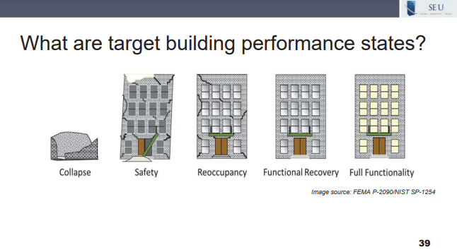
Resilient design applied to an individual building will most often result in a “functional recovery” level performance goal. Functional recovery is a performance state where a building performs and is maintained, or restored, to safely and adequately support the basic intended functions associated with the pre-disaster use or occupancy. This performance goal is a step above reoccupancy, which is a performance state in which a building is maintained, or restored, to allow safe re-entry for the purpose of providing shelter or protecting building contents. A building in the reoccupancy state does not provide the same level of recovery opportunity to the community. A building in the functional recovery state is more useful to a recovering community because economic drivers and shelter are both provided in the same space.
As the design community continues to pursue resilience and resilient design concepts, structural engineers can actively contribute to planning discussions, building performance expectations, and being aware of benefits associated with performance-based design. Incorporating performance-based designs will become more prevalent as building codes and standards evolve, focused on minimizing the damage associated with adverse events.
29 Jan / 2023
AISI Standards
In 2016, the North American Specification for the Design of Cold-Formed Steel Structural Members underwent a major reorganization to be more in-line with the AISC Specification for Structural Steel. Are you aware of the current AISI standards available and where to find design criteria for structural members or framing systems?
In the December 2022 SEU session, Roger LaBoube, PhD, PE, from Missouri University of Science and Technology, presented Cold-Formed Steel Standards (2022). Roger noted the available cold-formed steel design standards and identified changes to these standards as adopted by IBC 2021. He also clarified the interdependence of the cold-formed steel framing standards and the cold-formed steel specification.
While giving an overview of the North American Standards for Cold-Formed Steel Structural Framing, Roger walked through the AISI Standards, what is included in them, and recent changes made to the standards. Specifically, Roger addressed the difference between AISI S100 which is the North American Specification for the Design of Cold-Formed Steel Structural Members and AISI S240 which is the Cold-Formed Steel Structural Framing standard.
Roger explained the rationale for the development of AISI S240. While AISI S100 gives criteria for designing an individual member or connection, AISI S240 was developed to address the design criteria of a system. To hear Roger explain several examples of when to refer to S240 as opposed to S100, watch this short 5 minute video:
AISI S100 and S240 are available for FREE download, along with the other AISI standards on the Free Publications page on the Cold Formed Steel Engineers Institute website.

Doug Hoffman, PE, Vulcraft

Ben Pitchford, PE, New Millenium Building Systems
In November 2022, SEU welcomed Ben Pitchford, PE, from New Millenium Building Systems, and Doug Hoffman, PE, from Vulcraft, to present Roof Design with Special Profile Joists. Ben and Doug have designated MATHCOUNTS (Homepage | MATHCOUNTS Foundation) for our SEU Speaker Inspires donation for the month.
In 1983, NSPE helped established MATHCOUNTS, a non-profit organization promoting middle school programs to build confidence and improve attitudes about math and problem solving. Their approach is to make learning math fun and help encourage students to embrace challenges.
Thank you, Ben and Doug, for helping structural engineers with your SEU session, and for your designation of MATHCOUNTS as our SEU Speaker Inspires Organization of the Month!
SEU began the SEU Speaker Inspires program in 2015 as a way to “pay it forward”, enabling our speakers to designate a charity/organization of their choice for SEU to make a donation to help improve our world.
23 Dec / 2022
High Pitched Roof Joist Designations
Can SJI load tables be used to select roof joists on high pitched roofs? How does the specifying engineer denote these pitched joists and ensure they are designed for the required roof loads?
In the November 2022 SEU session, Ben Pitchford, PE, from New Millennium Building Systems, and Doug Hoffman, PE, from Vulcraft, presented Roof Design with Special Profile Joists. Ben and Doug identified important unique considerations when specifying steel joists and Joist Girders with pitched chords or radiused chords. They described the factors that impact special profile steel joists and gave tips to ensure designers can avoid additional RFIs during their projects.
During the presentation, Ben discussed the proper way to specify joists with a pitched top chord slope greater than ½:12. These joists can no longer be specified using an SJI load table designation, but rather they should be specified using a LOAD/LOAD designation. SJI does provide some load tables for LOAD/LOAD designated joists.
Ben explained the following design example to clarify how to designate these types of joists:

Ben previously discussed that double-pitched joist designation depth is taken at the ridge, as opposed to single pitch joists whose designation depth is at mid-span. Once the depth is established from the roof geometry, the type of joist is selected, and then the LOAD/LOAD designation is calculated using the joist spacing. The designation is displayed as the TOTAL LOAD / LIVE LOAD. Thus, with a 6 ft spacing and a total load of 40 psf and a live load of 20 psf, the correct designation for this double-pitched top chord joist is 102DLH240/120.
Ben also noted that structural engineers have the option to designate a joist as “SP” to indicate a special joist which should be designed by the joist manufacturer. These joists, as shown in the example below, can have varied shapes and slopes and the specifying engineer should provide a complete load diagram for the joist manufacturer to avoid RFIs during the project.
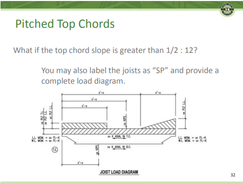
Engineers have multiple options to use joists and Joist Girders on projects with sloped roofs, and properly specifying these joists will eliminate confusion during the construction administration process. The Steel Joist Institute can provide further guidance through their Resource Library on their website which covers all subjects relating to steel joists.
23 Dec / 2022
“SEU Speaker Inspires” Organization of the Month: Rebuilding Together – Hurricane Ian Fund

Connor Lester, PE
Mary Nunneley, PE
In October 2022, SEU welcomed Connor Lester, PE, and Mary Nunneley, PE, from Simpson Strong -Tie, to present Prequalification & Code Approval of Proprietary Connections. Connor and Mary have designated Rebuilding Together’s Hurricane Ian Fund (Hurricane Ian | Rebuilding Together) for our SEU Speaker Inspires donation for the month.
Connor and Mary shared “We choose this organization because as structural engineers we are often faced with the realities of how building codes, our design practices and our ever evolving understanding of building response to catastrophic events, affect the lives of real people every day. Our codes are often focused on the principles of life safety, but it can be just as important to consider how building resilience and functional recovery play a role in our designs. Rebuilding Together is focused on repairing homes, revitalizing communities and rebuilding the lives of those affected by Hurricane Ian. We hope that our donation will provide relief to families and improve lives.”
Thank you, Connor and Mary, for helping structural engineers with your SEU session, and for your designation of Rebuilding Together’s Hurricane Ian Fund as our SEU Speaker Inspires Organization of the Month!
SEU began the SEU Speaker Inspires program in 2015 as a way to “pay it forward”, enabling our speakers to designate a charity/organization of their choice for SEU to make a donation to help improve our world.
18 Nov / 2022
“SEU Speaker Inspires” Organization of the Month: Structural Engineers Foundation (SEF) of SEAOI
Scott Nacheman, MSc.Eng., AIA

Perry Pinto, PE
In August 2022, SEU welcomed Scott Nacheman, MSc.Eng., AIA, and Perry Pinto, PE, from JS Held, to present South Florida Pedestrian Bridge Collapse Forensic Investigation. Scott and Perry have designated Structural Engineers Foundation (SEF) of SEAOI (Structural Engineers Foundation (SEF) | SEAOI) for our SEU Speaker Inspires donation for the month.
Scott shared, “The SEF has a rich history of funding scholarships, awards, publications, research, and unique lectures regarding cutting-edge projects and industry practices, all with the goal of improving structural engineers and structural engineering. We are honored to be able to share this donation with the SEF to help further their mission of enhancing both the current and future generations of structural engineers.”
Thank you, Scott and Perry, for helping structural engineers with your SEU session, and for your designation of SEF of SEAOI as our SEU Speaker Inspires Organization of the Month!
SEU began the SEU Speaker Inspires program in 2015 as a way to “pay it forward”, enabling our speakers to designate a charity/organization of their choice for SEU to make a donation to help improve our world.
18 Nov / 2022
Stiffness Modifiers in FEM
How do you establish appropriate cracked section factors for your structural elements when modeling reinforced concrete structures? Do you typically follow ACI, assume everything is cracked, run the model, and call it a day? How can you be sure the stiffness modifiers you selected for your structural elements mimic reality?
In the September 2022 SEU session, Sam Rubenzer, PE, SE, from FORSE Consulting, presented Verifying Software Results to our SEU group. Sam explained some methods used in software for load generation and how to verify their accuracy. He showed how to develop methods to determine what to expect from analysis results and ways to create checklists to assist with finding modeling or analysis errors. He also covered code checks performed by software programs and highlighted items that are not checked.
Sam noted that a prudent approach to verifying software results includes establishing simple models to approximate results and then moving toward a more complex product to compare with the original model results. For engineers using finite element modeling for reinforced reinforced concrete buildings, this task involves assigning effective stiffness factors for various structural elements. Some engineers assign the same cracked factors based on element type, but this simplification could be inaccurate in some instances. Sam recommended an article which identifies the importance of establishing accurate cracked section factors during analysis. Effective Stiffness for Modeling Reinforced Concrete Structures, by John-Michael Wong, PhD, SE, Angie Sommer, SE, Katy Briggs, SE, and Cenk Ergin, PE, appeared in Structure Magazine in January 2017. Within the article, a useful table presents the various stiffness modifiers for elements for many different building codes throughout the world. This table highlights the complexity that is inherent in attempting to accurately model these structural elements in analysis software and how a more detailed level of thought is required to produce an accurate building model.
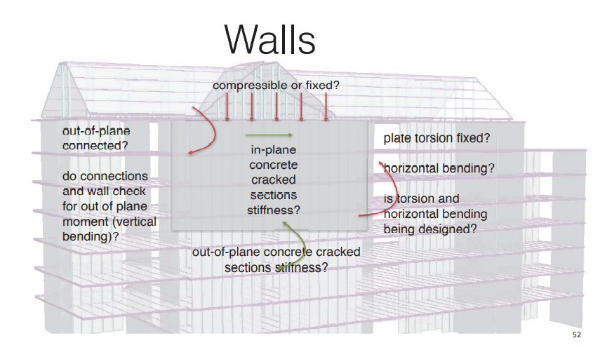
The following slide shows one example from Sam’s presentation of a building wall and the many considerations that should be taken when modeling. What is the purpose of the wall? Is it being used more in bending, shear or axial? Sam noted the engineer should consider the fixity, bracing and purpose of the element when modeling in software and some elements may need varying stiffness factors for in-plane and out–of-plane loads.
Since cracked section factors significantly affect the results of software analysis, engineers need to understand the importance of selecting appropriate factors for their structural elements. This process can be iterative since the assumed stiffness of various elements influences the dynamic response of the structure and can change the results of the analysis and the effective stiffness. As Sam suggested, moving toward a more complex model that mimics reality should be a reasonable exercise, however, modeling an exact replica with each element having a unique cracked section factor would be inefficient. This article offers guidance from various building codes on appropriate cracked section factors and should be a quick reference when developing complex finite element models.
10 Nov / 2022
“SEU Speaker Inspires” Organization of the Month: NCSEA Diversity in Structural Engineering Scholarship

Emily Guglielmo, SE, PE, Martin/Martin
In May 2022, SEU welcomed back Emily Guglielmo, SE, PE, from Martin/Martin, to present Wind Loads: Updated Frequently Asked Questions. Emily has designated NCSEA Diversity in Structural Engineering Scholarship (NCSEA Diversity in Structural Engineering Scholarship) for our SEU Speaker Inspires donation for the month.
Emily shared, “I chose the NCSEA Diversity in Structural Engineering Scholarship because I believe we must do a better job to encourage the next generation, regardless of race, gender, or socioeconomic background, that structural engineering is a viable career option for them.”
Thank you, Emily, for helping structural engineers with your SEU session, and for your designation of NCSEA Diversity in Structural Engineering Scholarship as our SEU Speaker Inspires Organization of the Month!
SEU began the SEU Speaker Inspires program in 2015 as a way to “pay it forward”, enabling our speakers to designate a charity/organization of their choice for SEU to make a donation to help improve our world.