26 Aug 2022
Wind Loads on Balcony Handrails
Balcony handrails are commonplace for large residential buildings, and they come in a variety of forms. While some are solid glass or metal, others may be more porous in nature, thus the design of these appurtenances for wind becomes more complex.
In the May 2022 SEU Session, Emily Guglielmo, SE, PE, from Martin/Martin Inc., presented Wind Loads: Updated Frequently Asked Questions. Emily explained how to deal with commonly encountered wind load situations that are not fully addressed in the code. She also identified the latest code updates and examined some complicated wind load provisions and how they relate to real world examples.
Emily noted that the most frequently asked question in regard to wind pressures that she receives is which wind load should be applied to these common balcony handrails. To hear her explanation for a reasonable rationale for the design of handrails, watch this short 4 minute video:
Using this approach, engineers can more accurately determine if the geometry of the handrail will induce a suction pressure on the leeward side, or whether the handrail acts more like a solid windward wall on the face of the building. Emily also provided an excellent resource to justify a reduction in the windward surface area for perforated materials which was developed by the chain link fence industry. This document indicates that a reduction can be taken unless the porosity of the material is less than 10% which would require the area be assumed solid.
Emily’s guidance helps clarify this often murky subject since the code does not give clear answers on wind loads for balcony handrails, and using the porosity of the material may help reduce these wind loads when applicable.
26 Aug 2022
2021 SDPWS Highlight: CLT Now Included
Are you aware of the new additions to the 2021 Special Design Provisions for Wind and Seismic (SDPWS)? Several changes have been incorporated in the 2021 edition, which is the first revision since 2015 for this IBC-referenced document. The provisions were developed by AWC’s Wood Design Standards Committee, and new sections have been added to Chapter 4 to include more guidance when using cross-laminated timber (CLT).
In the July 2022 SEU session, Lori Koch, PE, from American Wood Council, presented Special Design Provisions for Wind and Seismic (SDPWS) 2021 Updates. Lori identified the major changes between the 2021 SDPWS and previous editions. She highlighted the new format for the shear wall and diaphragm capacity tables and described the new table for out-of-plane wind resistance for OSB and plywood wall and roof sheathing. Also, she introduced the new shear wall and diaphragm provisions for cross-laminated timber (CLT).
Lori noted that Chapter 4 of SDPWS now contains sections 4.5 Cross-Laminated Timber (CLT) Diaphragms and 4.6 Cross-Laminated (CLT) Shear Walls. Section 4.5 is a one-page standard whose requirements are largely an engineered approach which references the National Design Specification (NDS) for the design of CLT diaphragms.
Section 4.6 references the newly added Appendix B for design provisions applicable for wind and seismic. Appendix B includes the mandatory requirements for CLT shear walls and defines two systems: CLT shear wall and CLT shear wall with shear resistance provided by high aspect ratio panels only. The requirements mandate platform construction where CLT floor panels bear on CLT walls below. There are limits to the aspect ratio of the panels and which connectors may be used, and uplift due to overturning must be resisted by hold-downs. There is an exception to the requirements in Appendix B for buildings in low seismic hazard areas which do not exceed 65 feet in height.
Lori noted that extensive testing to CLT shear walls was conducted in accordance with FEMA P-695 in order to identify seismic performance factors of CLT shear walls as a new seismic force resisting system (SFRS). The methodology used is consistent with the primary “life safety” performance objective of seismic regulations in model building codes. To view the results of this FEMA P-695 report, click here.
With the addition of the CLT sections to the 2021 SDPWS, engineers now have a codified standard for use in their wood structures. To download the new updates to the 2021 SDPWS or to purchase your own copy, click visit the AWC website.
26 Aug 2022
“SEU Speaker Inspires” Organization of the Month: Structural Engineers Association of Utah Scholarship Fund

Barry Arnold, PE, SE, ARW Engineers
In June 2022, SEU welcomed Barry Arnold, PE, SE, from ARW Engineers, to present Base Plates, Embeds, and Disasters, Oh My! Barry has designated Structural Engineers Association of Utah Scholarship Fund (Structural Engineers Association of Utah – Scholarships (seau.org)) for our SEU Speaker Inspires donation for the month.
Barry shared, “As a student struggling to pay for tuition and books, attending classes, completing homework, maintaining a good family life, and working full-time, I remember how grateful I was to receive a scholarship. Receiving a scholarship reduced my anxiety and the pressure I felt by easing my financial burdens. I hope whoever receives this scholarship will benefit from the financial assistance as I did when I was a student.”
Thank you, Barry, for helping structural engineers with your SEU session, and for your designation of Structural Engineers Association of Utah Scholarship Fund as our SEU Speaker Inspires Organization of the Month!
SEU began the SEU Speaker Inspires program in 2015 as a way to “pay it forward”, enabling our speakers to designate a charity/organization of their choice for SEU to make a donation to help improve our world.
18 Jul 2022
Wind Loads on Rooftop Screenwalls
Which ASCE provision do you typically use when designing a rooftop screenwall for wind loads? Several options have been used by structural engineers in the past, but the best option has been debatable since the code has not explicitly spoken on the subject. New guidance in ASCE 7-16 helps clarify this frequently asked question.
In the May 2022 SEU Session, Emily Guglielmo, SE, PE, from Martin/Martin Inc., presented Wind Loads: Updated Frequently Asked Questions. Emily explained how to deal with commonly encountered wind load situations that are not fully addressed in the code. She also identified the latest code updates and examined some complicated wind load provisions and how they relate to real world examples.
One of the most frequently asked questions, in regard to wind load provisions, is what wind load should engineers use for a roof top screen wall or equipment? Emily noted that while there are several commonly used provisions for these calculations, there is an approach that may be considered ‘more right’ than others. Typically, engineers have used one of the following three different options for determining the wind loads on rooftop screen walls:
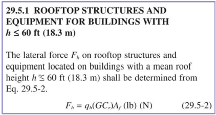
A. Rooftop Structures and Equipment
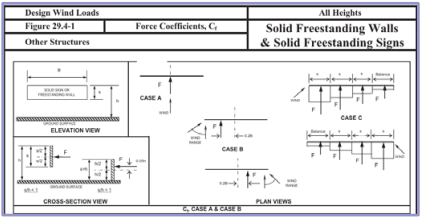
B. Solid Freestanding Signs
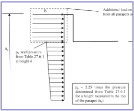
C. Parapet Pressures
While Emily noted that none of these approaches are necessarily incorrect, the code now offers some guidance in the commentary:
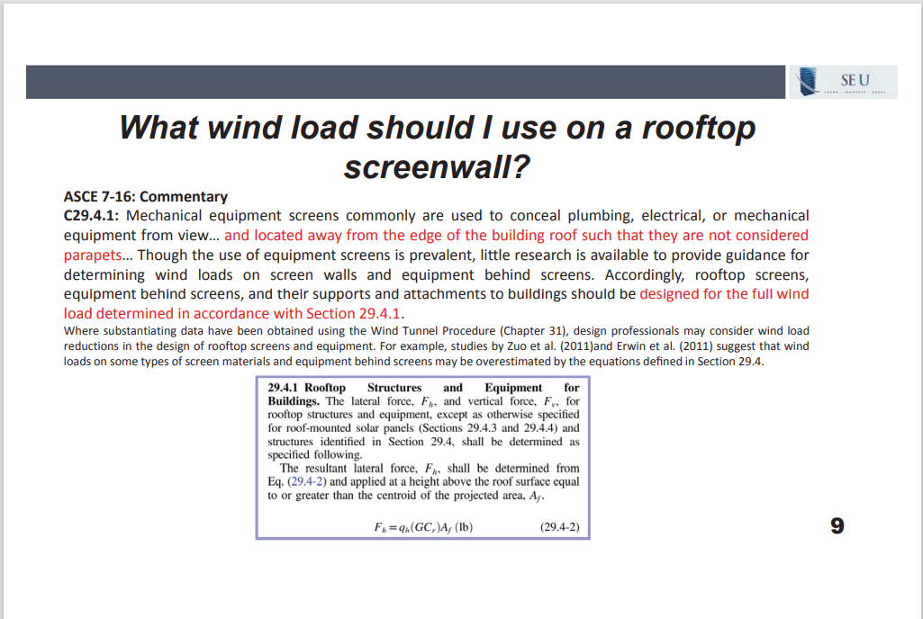
New to the commentary in ASCE7-16, C29.4.1 states that “Mechanical equipment screens… located away from the edge of the building roof such that they are not considered parapets…” should use the wind load determined with Section 29.4.1. This statement implies that if the screen is located near the edge of the roof, that perhaps a parapet pressure might be more appropriate. Emily noted that it would be reasonable to conclude that if the screen wall falls within the typical rooftop wind zone, then Sections 29.4.1 should be applied and when the screen falls within an edge or corner zone, a parapet pressure could be more appropriate.
This new addition to the commentary with the 2016 revision helps provide more clarity to this frequently asked question, and engineers now have more guidance for common rooftop screens and equipment.

Carine Magalhaes Leys, Odeh Engineers
In April 2022, SEU welcomed Carine Magalhaes Leys, from Odeh Engineers, to present 2022 Post-Tensioning Design: Finite Element Method-Based Solutions. Carine has designated GRAACC Support Group for Adolescents and Children with Cancer in Brazil (https://www.globalgiving.org/projects/better-chances-of-cure-for-childhood-cancer-in-br/) for our SEU Speaker Inspires donation for the month.
Carine wished to support children in Brazil where there is an estimated 16,000 new cases of cancer in every 100.000 children and adolescents. Cancer is the first leading cause of death by disease in the population up to 19 years old. The GRAACC manages and maintains a hospital that offers diagnostic, treatment and after treatment for children and adolescents with cancer in Brazil.
Thank you, Carine, for helping structural engineers with your SEU session, and for your designation of GRAACC Support Group for Adolescents and Children with Cancer as our SEU Speaker Inspires Organization of the Month!
SEU began the SEU Speaker Inspires program in 2015 as a way to “pay it forward”, enabling our speakers to designate a charity/organization of their choice for SEU to make a donation to help improve our world.
30 Jun 2022
Resources for Improving Leadership Skills
Natural born leaders are a rare breed, but many skills needed to empower and motivate teams can be learned and improved. However, it takes great intentionality to make meaningful change. Changing patterns and behaviors can be a challenge, but learning the art of building successful working relationships will pay dividends over the course of a career. Check out these helpful articles and resources which aim to identify excellent leadership qualities and tips to hone your skills:
5 Traits That Will Instantly Point to Someone With Bad Leadership Skills | Inc.com
Why The Distinction Between Leader And Manager Matters (forbes.com)
How Can You Be Sure Someone Has What It Takes to Lead People? Look for 4 Rare Habits | Inc.com
9 Skills to Manage Your Team | Blog.SHRM.org
The Leadership Skills To Be Learned From Parenting – Young Upstarts
28 Jun 2022
Long Term Deflections for Concrete Slabs
Have you ever had a phone call from a building owner whose occupants are complaining of cracked partitions or noticeable slopes in their office flooring? Building occupants are quick to notice when doors or cupboards get jammed, wall finishes crack, or concrete slabs show cracks larger than ordinarily expected, and many of these serviceability issues are the result of long-term deflections of the concrete floor.
In the February 2022 SEU Session, Dave Adams, PE, SE, from BWE, Inc., presented Serviceability for Concrete Slabs. Dave covered a variety of topics addressing serviceability of slabs including strategies for improving the performance of concrete, short- and long-term deflections, the influence of reinforcement on potential cracking, prestressed tendon layout, and the effects of floor vibrations.
Dave explained how to calculate long-term deflections and important considerations when predicting the sustained dead and live load on the slab. To hear Dave review the process when considering long-term deflections, click on the following 3 minute video:
Long-term deflections are an important consideration to the serviceability of a concrete slab, and Dave clarified the use of the various factors and multipliers which help predict the future deflections. Accurately assessing the sustained load on the slab can be challenging, however Dave offered reasonable predictions for which live-loads should be considered “sustained.”
While strength considerations tend to get the most attention during slab designs, serviceability issues can render a slab unusable for its intended purpose. It is essential that short- and long-term deflections be considered to ensure the slab does not cause future alarm to occupants, cracking or movement of partitions, or issues with furniture or fittings within the structure.
30 May 2022
The Ethics of Advertising
What kinds of ethical dilemmas could arise from a straightforward brochure offering your engineering services? What legal rules exist to regulate professional advertising? Are you familiar with the ethical guidelines of any professional society to which you are a member?
In the March 2022 SEU session, Matthew Rechtien, PE, Esq., from Walter P Moore, presented our 2022 Engineering Ethics Update: The Ethics of Competition. Matt explained how qualifications-based selection works and its legal and ethical implications. He also reviewed the legal and ethical implication of gifts and reviewed the ethical constraints on advertisement.
Matt explored the legal limits in regard to professional advertising for a variety of states and the general consensus is that advertisements must be truthful and not deceptive or misleading. Some states include more specific language regarding resumes, brochures, or solicitations, however, the general legal requirements for professional advertisements focus on truthfulness. Truthful advertisement is protected “commercial speech” guaranteed by the 1st and 14th Constitutional Amendments, and Matt noted that the Supreme Court has stricken most attempts at regulation of professional advertising.
While the Constitution may govern our legal rights to professional advertising, the First Amendment does not apply to private regulations such as those set forth by voluntary professional societies. Ethical guidelines drafted by agencies such as NSPE and ASCE certainly require a higher benchmark for their membership. For instance, NSPE requires that “Engineers shall not attempt to obtain… professional engagements by … other improper or questionable methods” and ASCE requires engineers to “uphold the honor, integrity, and dignity of the profession…” These requirements certainly create an additional burden of responsibility for engineers to advertise in such a way as to not impugn the profession itself while also meeting the legal obligation of being truthful and not deceptive.
Both NSPE and ASCE publish examples of previous ethical dilemmas considered by their board members. NSPE’s Board of Ethical Review publishes all of their opinions, and you can search by topic for previous rulings. ASCE’s Committee on Professional Conduct also publishes cases that have been considered which can be found monthly in Civil Engineering Magazine or you can search by topic on their website. For example, Matt used a case example that was similar to a case highlighted by NSPE, as shown in the following slide:
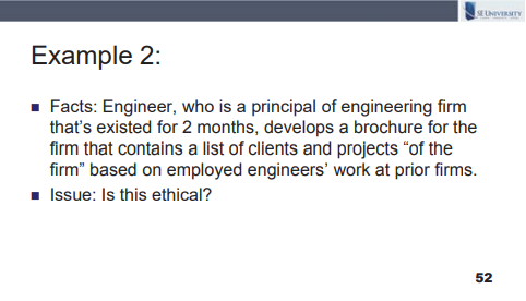
Matt noted that NSPE “…was deeply troubled by the manner in which the Engineer undertook to promote his new engineering firm because we believe there was a clear effort on the part of the Engineer to engage in misleading and deceptive acts…” In the ruling by NSPE, the committee notes how the engineer violated its Code of Ethics and ways in which the engineer could have avoided the charge of being misleading in their advertisement.
Both NSPE and ASCE can offer insight on precedents set by these ethics committees when engineers have encountered ethical dilemmas in their advertising. While advertising may not be as heavily regulated as ethical quandaries such as gifts to elected officials or bribery, there are still many instances where improper advertisements for engineering services have resulted in disciplinary actions from these voluntary societies. Be sure to check out these excellent resources of past cases, and avoid any ethical infractions in your resumés, brochures, or website advertising.

Matthew Rechtien, PE, Esq., Walter P. Moore
In March 2022, SEU welcomed Matthew Rechtien, PE, Esq., from Walter P. Moore, to present 2022 Engineering Ethics Update: The Ethics of Competition. In prior years, Matt has designated Friends of Perryville Battlefield (https://www.friendsofperryville.org) for our SEU Speaker Inspires donation for the month and he has chosen to do the same in 2022.
Matt shared, “On October 8, 1862, nearly 8,000 Americans fell in the drought-parched Chaplin Hills of Kentucky during the Battle of Perryville. Perryville played a pivotal role in our nation’s most impactful event. Although the clash is oft-forgotten, those Americans should be remembered and that sacred ground, one of the most pristine civil war battlefields remaining, should be protected. The Friends of Perryville Battlefield is committed to both missions, which I am humbled to advance.”
Thank you, Matt, for helping structural engineers with your SEU session, and for your designation of Friends of Perryville Battlefield as our SEU Speaker Inspires Organization of the Month!
SEU began the SEU Speaker Inspires program in 2015 as a way to “pay it forward”, enabling our speakers to designate a charity/organization of their choice for SEU to make a donation to help improve our world.
Engineers are often more familiar with strength provisions for concrete slabs, but building codes require adequate strength and serviceability. Excessive cracking and sloping or bouncy floors can be a nuisance and render a building unusable for its intended purpose. Thus, engineers should be familiar with the available resources providing guidance for serviceability issues above and beyond the basic requirements in the building code.
In the February 2022 SEU Session, Dave Adams, PE, SE, from BWE, Inc., presented Serviceability for Concrete Slabs. Dave covered a variety of topics addressing serviceability of slabs including strategies for improving the performance of concrete, short- and long-term deflections, the influence of reinforcement on potential cracking, prestressed tendon layout, and the effects of floor vibrations.
Throughout the presentation, Dave offered resources to learn more about serviceability of concrete slabs and to find additional design examples for reference. Most of the presentation was based on guidelines in our usual Design Codes, such as 2018 International Building Code, ACI 318-14 Building Code Requirements for Structural Concrete, and ASCE/SEI 7-16 Minimum Design Loads and Associated Criteria for Buildings and Other Structures. But many other resources are available to provide further guidance for serviceability which tends to get less coverage in the main Design Codes.
Since mix design and placement can greatly affect the performance of concrete slabs, Dave noted that ACI 209R Prediction of Creep, Shrinkage, and Temperature Effects in Concrete Structures offers guidance for the practicing engineer on concrete mix designs and how to plan for serviceability concerns. ACI SP-20, Causes, Mechanisms, and Control of Cracking in Concrete is another useful document to prevent excessive short- or long-term cracks in concrete slabs along with 224R-01 Control of Cracking in Concrete Structures.
Two excellent resources that offer a detailed understanding of prestressed concrete member deflections are the PCI Design Handbook and Deflections of Prestressed Concrete Members from the ACI Journal Proceedings, V60, No.12, 1963. Also, Dave recognized the ACI Journal Proceedings V6, No, 6, from June 1963 Load-Balancing Method for Design and Analysis of Prestressed Concrete Structures by T.Y. Lin. This article is useful for learning more about determining acceptable tendon profiles for prestressed concrete and the load balancing method based on elastic prestressed concrete beam theory.
For vibration control of concrete slabs, engineers can refer to AISC Design Guide 11: Floor Vibrations Due to Human Activity and Design Guide for Vibrations of Reinforced Concrete Floor Systems from CRSI. Vibration issues are often subjective, but they can have important ramifications on the usefulness of concrete floors for a variety of activities.
Some of these resources are available free of charge, and others are available for purchase, but all of these materials are helpful to eliminate serviceability concerns in concrete slabs.