22 Jun 2018
Resources for Wood Construction Issues
How often have you visited a job site for a wood structure you have designed, only to find the contractor has used a different fastener than specified? Or perhaps you noticed a seasoning check on a glulam beam and were unsure whether it could jeopardize the integrity of the beam? With so much flexibility inherent to wood construction, there tends to be many “field fixes” or unapproved fastener patterns which then lead to questions about whether these fixes are structurally sound. Having the resources you need when these situations arise can help avoid these issues and may provide additional information to help avoid callbacks in the future.
In the May 2018 SE University session, Robert Kuserk, PE, from APA – The Engineered Wood Association, presented Frame for Success – Best Practices for Wood Buildings. Robert offered several resources for use when designing a wood framed structure.
Robert reviewed the guidelines regarding seasoning checks in glulam beams and recommended APA’s Technical Note – Owner’s Guide to Understanding Checks in Glued Laminated Timber (Form F450) as a resource when evaluating seasoning checks in wood beams. To learn more about when seasoning checks may be of concern, please watch this short video.
Another resource which can be useful when designing wood structures is the International Staple, Nail, and Tool Association ICC-ES Evaluation Report ESR-1539. This publication has extensive tables and strength values for nails and power driven staples. Robert also suggested using their website www.isanta.org for additional fastener information.
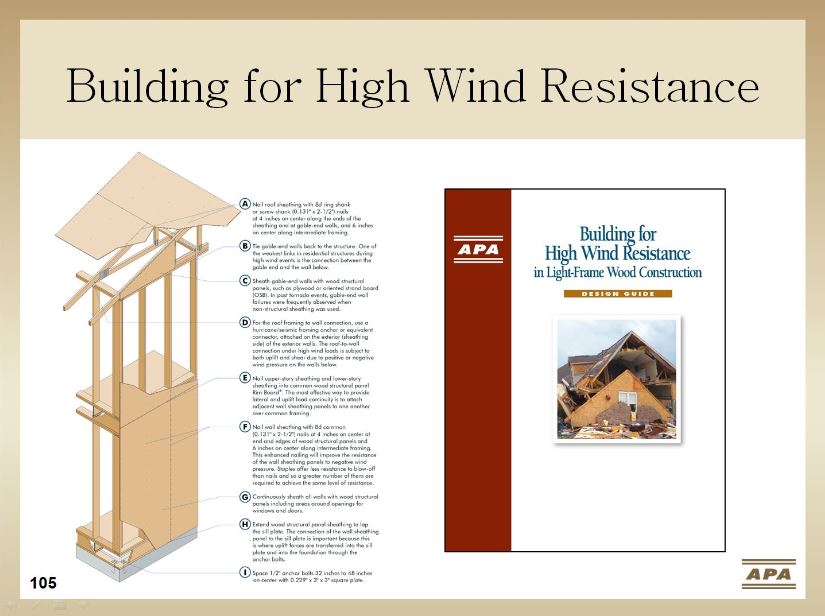
During the session, Robert highlighted important aspects of a wood structure that should be reinforced for high wind events and offered APA’s Building for High Wind Resistance in Light Frame Wood Construction (Form M310). Robert included the following slide which outlines the most critical connections in wood buildings, and further connection details and recommendations are available throughout this publication. Click on the slide to print your own copy.
Using a variety of resources beyond the scope of the NDS, structural engineers can develop a “Best Practices” approach to wood construction. When problems arise in the field, being familiar with the resources available from APA and other organizations can help address the issues quickly and efficiently. Visit www.apawood.org for construction guides, technical details, and much more.
Are you a Recent Graduate or Student in Civil/Structural Engineering who would like to learn additional technical information to help you start your career as a structural engineer? Transitioning from student to entry-level engineer has a learning curve associated with it. But with proper preparation and a commitment to continued learning, your entry-level job can lead to a rewarding career in structural engineering.
SE Apprentice can help you on your path to success! This series of recorded sessions aims to present ideas and concepts not typically learned in class, and combine these with real world knowledge of how a building and project come together, to help give students and new graduates an idea of what to expect on a project they would work on in the office.
These sessions are available for both students and new/recent grads. Please visit www.seapprentice.com to access the sessions. While the SE Apprentice series is available at no cost for students, companies that find these sessions helpful for their newly hired engineers can elect to donate to Structural Engineers of Ohio (SEAOoO) Educational Awards Fund as a way to ‘pay it forward’ for the future generation of structural engineering students. (but this is not required)
SE Solutions & SE University hopes this series benefits companies with new engineers as well as students wanting to be more prepared to start their career upon graduation.
Using post-installed adhesive anchors is commonplace in concrete construction and especially in renovations of concrete structures. However, field conditions can often dictate changes to the original design, and anchors are often relocated due to unforeseen circumstances. If you have been a design engineer for any length of time, you have undoubtedly encountered the situation where a hole was misdrilled, or the contractor is requesting to relocate the anchor due to existing rebar or or other conflicts. Having this happen on a project may lead to the question – What are the effects of the abandoned hole on the newly installed anchor?
In September 2017, Kevin Davenport, PE with Simpson Strong-Tie gave a presentation on Code Provisions for Post-Installed Adhesive Anchors into Concrete for SE University. Kevin reviewed recent changes in ACI addressing adhesive anchors and the new requirements for design engineers, as well as new mandates for installation and inspections. Kevin also responded to a variety of audience questions in reference to adhesive anchors, and the topic of anchor installation near mis-drilled holes was addressed.
Recently, Simpson Strong-Tie conducted several laboratory tests on adhesive anchors in tension adjacent to abandoned holes. These tests helped to provide some guidelines for design engineers when dealing with unforeseen field conditions such as misdrilled or abandoned holes near tension anchors. Kevin provided this memorandum from Simpson StrongTie which summarizes the results of the testing, and also provided this blog post which further describes each anchor and situation that was tested in their ISO 17025-accredited anchor testing laboratory in Illinois. Using these spacing and reduction factor guidelines, engineers can more accurately consider the effects of misdrilled holes and make appropriate recommendations when field conditions are not as anticipated.
Special moment frame design can be daunting for the engineer that is not completely familiar with the many code provisions that ensure they can withstand high seismic activity. Even the most seasoned seismic designers can benefit by reviewing the additional design and detailing requirements occasionally to be sure nothing is missed when designing these highly complex frame systems and connections.
In June 2017, Matt Mester, PE, SE from SidePlate Systems, Inc. presented Moment Frames: Design and Detailing per AISC 341 and 358 for SE University. His presentation included moment frame and connection design principles, and he compared and contrasted the various code requirements for each type of moment frame. Matt also reviewed the use of prequalified moment connections from AISC 358.
During his presentation, Matt referenced the NEHRP Seismic Design Technical Brief No. 2. This brief specifically addresses the design and detailing of special moment frames and their connections to ensure they can safely withstand severe earthquake shaking while experiencing substantial inelastic deformation. Included in the brief are analysis and design guidance, additional requirements, and detailing and constructability issues. This more in depth discussion on special moment frames is a great reference for engineers that typically practice in high seismic zones and for engineers that may just be getting started in the design of special moment frames.
19 Jul 2017
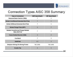
AISC 358 Connection Types and Limits
Connection design can get complicated when a building is located in a high seismic region. These connections require a significant amount of inelastic deformation in order to safely resist strong seismic activity. After the Northridge earthquake in 1994, many connection failures found in the aftermath allowed code officials to investigate and make changes to prevent these types of failures from recurring. One of the many results from this incident was the eventual development of the prequalified moment connections contained in AISC 358.
In June 2017, Matt Mester, PE, SE from SidePlate Systems, Inc. presented Moment Frames: Design and Detailing per AISC 341 and 358 for SE University. Matt reviewed all of the prequalified moment connections contained in AISC 358 and discussed the restrictions and limitations for when these connections can be used. He presented several useful charts which show each connection type included in AISC 358. Click on the slide below to access the 4 page file so that you can create your own quick reference chart for future seismic connection design.
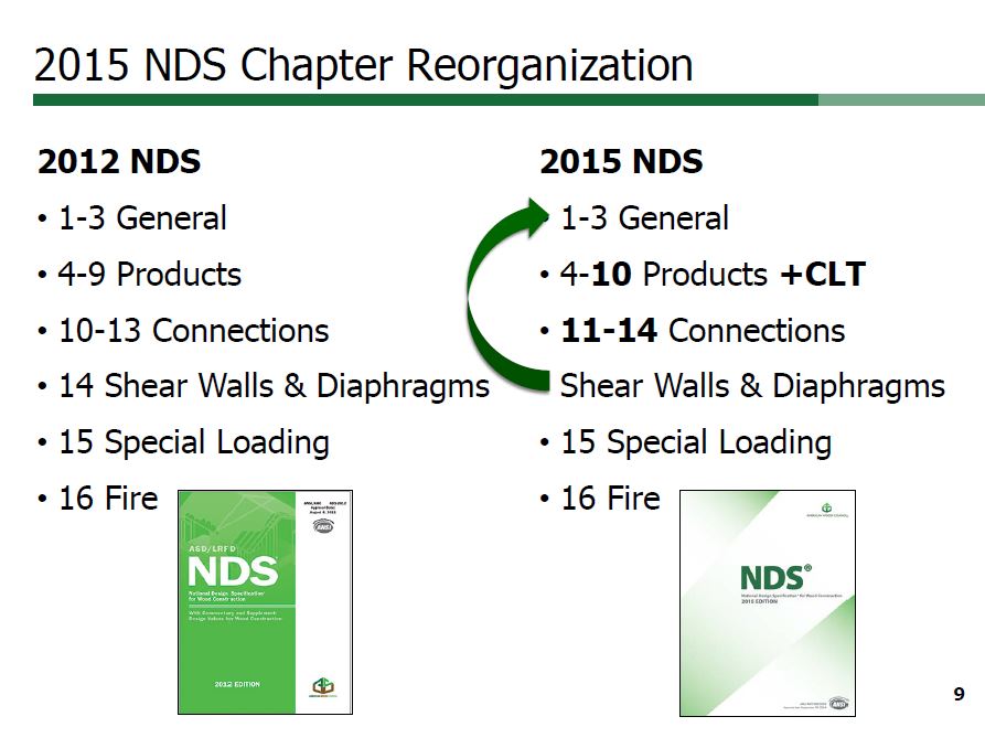
Have you seen some of the new mid to high-rise structures that are using cross-laminated timber? While the product has been used in Europe since the 1990s, it has more recently become available in the US and Canada. Now, with the incorporation of this new wood product in the 2015 NDS for Wood Construction, you can expect its availability to increase as more designers become aware of its structural properties.
In the April 2017 SE University Core Session, Lori Koch, PE from the American Wood Council addressed changes in the 2015 NDS for Wood Construction. While some are minor revisions, the most significant change to the 2015 NDS is the incorporation of Cross-laminated Timber (CLT). Lori acknowledged this new wood product has been used internationally for some time, and the NDS felt it was important to include a new chapter for CLT in the wood products section of the code. Chapter 14, which referenced design of shear walls and diaphragms from the 2012 NDS, was relocated and included in Chapter 1, so with the addition of Chapter 10 for CLT, the 2015 NDS still remains at 16 chapters.
Also, new to the NDS is terminology for Laminated Strand Lumber (LSL) and Oriented Strand Lumber (OSL). Chapter 8 on Structural Composite Lumber reflects the inclusion of these products in ASTM D5456. Chapter 16, Fire Design of Wood Members, was revised to include CLT.
Additionally, there were updates to design values for southern pine within the NDS Supplement. For a complete listing of changes to the 2015 NDS including references to CLT, read this article from STRUCTURE Magazine or visit www.awc.org for complete information about the 2015 NDS.
04 Jan 2017
Specifications for Steel Castings
Have you been involved in a project with extensive architecturally-exposed steel connections or complex geometric constraints? Or, have you ever considered using standardized steel castings to improve seismic resistance in braced frame construction? Structural steel castings can be a benefit in all of these situations, but may not be as familiar to most engineers as traditional designs.
In the November 2016 SE University Supplemental Session, Carlos de Oliveira, M.A.Sc.,P.Eng., from Cast Connex Corporation, gave a talk on Structural Applications for Steel Castings. During this lunch and learn presentation, Carlos gave a brief history of the use of steel castings, explained how they are manufactured, and discussed when steel castings can be used to benefit the structural design. Both standardized and custom castings can be useful in solving complex structural geometry and connections, and are typically more aesthetically pleasing for the architect. Some of the structural designs shown in his presentation were truly impressive and may inspire some ingenuity in your next design.
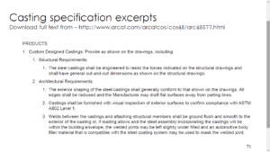
Using steel castings may be new to some structural engineers, however, Carlos gave some tips on specifying castings in the contract documents. For custom castings, the engineer and architect need to provide the overall dimensions, configuration, and relationship to other structural and architectural components on the drawings. Then, the engineer should include additional requirements within the specification to delegate the structural design responsibility to the casting supplier by outlining the structural performance requirements (ie. structural loading, structural connection to the castings, and machining requirements), as well as architectural performance requirements (ie. surface finish, and AESS welding requirements).
Carlos also provided some resources for using templates for these specifications for custom and standardized steel castings. These templates are a great tool to get started in specifying structural steel castings for your next project that includes complex geometry or architecturally exposed steel. Click on the slide below to view an excerpt from the specs or click visit http://www.arcat.com/arcatcos/cos48/arc48577.html to view example specs and catalogs for various steel casting connections.
26 Aug 2016
Accuracy in FTAO Wood Shear Wall Design Methods
Are you using the most accurate design method when you utilize Force Transfer Around Openings (FTAO) in your wood shear wall design? In the past, a variety of design techniques have been used to determine a rational analysis for wood shear walls, but recent research sheds some light on which methods are the most accurate for this type of design.
In the July 2016 SE University Core Session, Karyn Beebe, PE, LEED-AP, from APA – The Engineered Wood Association, covered Advancements in Force Transfer Around Openings for Wood Framed Shear Walls. During her presentation, Karyn highlighted recent results from research completed in a partnership between APA, University of British Columbia, and USDA Forest Products Laboratory. This research examined the internal forces generated during full-scale testing of a variety of walls with code-allowable openings of various sizes, and compared those forces with various design techniques and computer analytics that mimic testing data. The results proved to be very useful to determine which design methods would be most accurate for design engineers to implement in their FTAO wall designs.
As shown in the following table, a summary was created for 8 different wall configurations for FTAO, and compared the measured internal forces with the predicted forces from 4 different design techniques: The Drag Strut and Cantilever Beam Techniques, both developed by Zeno Martin, the Diekmann Technique, and the SEAOC/Thompson Technique. The first column shows the measured strap forces around the openings and the remainder of columns give the percent error in the predicted strap forces for the 4 methods. As you can see, the blocks highlighted yellow show an unconservative design (less than 100%), while the green blocks show an overly conservative design (greater than 300%). In most cases, the Diekmann and SEAOC/Thompson Techniques were useful in determining accurate strap forces. One outlier would be for Wall 6, which was a C-shaped panel, where the Drag Strut Technique was the best predicted response of strap forces.
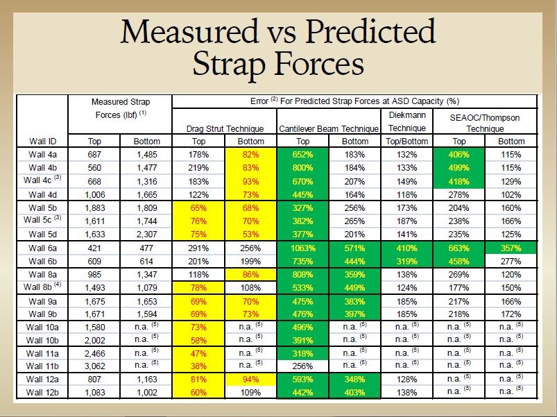
Click on the picture for an enlarged view
As a design engineer, this information can be used to identify which design techniques would result in the most efficient design for our clients, depending on which type of shear wall is being used on any given project. To learn more about this recent research, Karyn provided a link to a full set of testing results that can be viewed on the APA website’s Resource Library. Registration is required to access the file, but there is no charge to register and access other documents in the Resource Library.
Does your office have a system in place to ensure coordination between disciplines is addressed early and often throughout the design process? Are you frustrated by always having the same RFIs and Change Orders on your projects? The design process is just that – a process. However, many times we are met with the same issues that crop up over and over again. What can we do as the engineer-of-record to be proactive in the design process to alleviate the headaches of change orders and RFIs?
In the June 2016 core session of SE University, Carol Post, PE, SE, from Thornton Tomasetti, and Cathleen Jacinto, PE, SE, of FORSE Consulting and SE University, gave a talk on Best Practices to Improve Structural Construction Documents. During the presentation, Cathleen gave some suggestions to improve design team communication and coordination of bid documents and how to avoid some common pitfalls. Some common pitfalls she covered included:
- Edge of Slab
- Exterior Walls
- Mechanical Equipment
- Elevators
- Stairs
- Connection Design
As most of these items are typically determined late in the design process, it is inevitable that some information is not clear at bid time, and RFIs and Change Orders are the result. In the following video, Cathleen reviews the use of coordination checklists to address the most common modifications that result from the late selection of stairs and elevator equipment.
Using coordination checklists can be an effective tool to ensure these items are addressed early and communication continues throughout design, so that the engineer can make the most accurate assumptions to aid in preparation of bid documents. SE University clients have access to several design coordination checklists through the SEU Resource Center which may help to minimize changes during construction administration. To access these checklists, login to your SEU Resource Center, and follow the Innovation Hub to Helpful Tips and Resource Information.
For additional information about each of these checklists individually, please see the following blog posts:
by Jenny Schultz
Are you confident in your familiarity with the finite element software your office uses to design masonry building components? Do you know what the program design defaults are within your software and how to make changes when necessary? With software programs being frequently updated, it is important to stay up-to-date on the changes and features available to any programs you routinely use, and be informed of what is available in other programs on the market.
In May 2016, Sam Rubenzer, PE, SE, with FORSE Consulting, gave a presentation on Masonry Analysis and Design with FEA Software for SE University. While Sam’s entire presentation gave great insight into the utilization of FEA software to gain a greater understanding of the behavior of masonry building elements, he also specifically addressed the capabilities of various commercial software programs typically used by structural engineers to design masonry walls. Each program uses different features to help design engineers accurately model masonry elements, and while these features are continually being updated and changed, Sam’s overview shows what is currently available. Although not intended to be an all-inclusive review of each software program, Sam does point out key features that are useful specifically in masonry wall elements.
Typically, it is important to know how to modify the stiffness of masonry wall elements, and where the programs allow the engineer to make changes for cracked or uncracked walls. Horizontal or torsional bending may need to be considered in some masonry walls. Also, the ability to modify element connection releases is important, as well as the program’s ability to perform wall optimization or consider partial grouting. In the following 6 minute video, Sam demonstrates many of these topics and their applications in each of the following programs:
- RISA 3D
- SCIA Engineer
- TEKLA Structural Designer
- Ram Structural System